
Beyond the Single-Board Bottleneck: The Arduino Duo Methodology
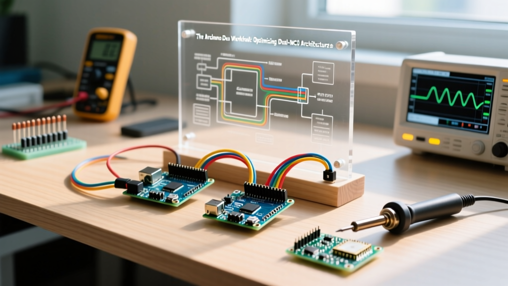
As embedded projects scale in complexity, makers inevitably hit the "single-MCU wall." You attempt to read high-frequency I2C sensors, drive a TFT display, and maintain a WebSocket connection simultaneously, only to find your main loop stuttering and buffers overflowing. Enter the Arduino duo workflow—a deliberate architectural choice to deploy two microcontrollers in tandem, separating real-time I/O operations from heavy computational or networking tasks.
Rather than migrating to a complex, bare-metal ARM Cortex-M7 board that lacks standard shield headers, the Arduino duo approach leverages the vast ecosystem of standard-form-factor boards. By assigning distinct roles to a "Brain" and a "Muscle" MCU, you eliminate interrupt latency, protect sensitive networking stacks from hardware-level faults, and drastically simplify debugging. In 2026, with the maturation of the Arduino UNO R4 and Nano ESP32 ecosystems, dual-board architectures are more accessible and cost-effective than ever.
Decision Matrix: When to Deploy an Arduino Duo Setup
Not every project requires two microcontrollers. Over-engineering a simple blink sketch with dual MCUs introduces unnecessary I2C overhead and power complexity. Use the following matrix to determine if your workflow requires an Arduino duo configuration.
| Project Requirement | Single MCU Viability | Arduino Duo Advantage |
|---|---|---|
| High-speed sensor polling + WiFi | Poor (Network stack blocks I/O) | Excellent (MCU 1 polls, MCU 2 transmits) |
| Legacy 5V Shield + 3.3V Logic | Moderate (Requires external shifters) | High (5V MCU drives shield, 3.3V MCU computes) |
| Motor Control + UI Display | Poor (PWM noise disrupts UI rendering) | Excellent (Galvanic isolation between domains) |
| Simple Data Logging | Excellent | Unnecessary (Adds BOM cost and power draw) |
Hardware Selection for 2026 Dual-MCU Builds
The most robust Arduino duo pairing in the current market utilizes the Arduino Nano ESP32 (approx. $22.50) as the networking Brain, and the Arduino UNO R4 Minima (approx. $20.00) as the I/O Muscle.
- The Brain (Nano ESP32): Handles WiFi 4, Bluetooth 5, RTOS multitasking, and cloud API payloads. Its dual-core Xtensa processor excels at string manipulation and JSON parsing.
- The Muscle (UNO R4 Minima): Built on the Renesas RA4M1, it features a 14-bit DAC, advanced hardware timers for precision motor control, and native 5V logic for driving legacy relays and actuators without level shifters.
Workflow Tip: Keep your physical footprints standardized. Using a Nano shield for the ESP32 and a standard Uno shield for the R4 allows you to use off-the-shelf prototyping plates, reducing custom PCB fabrication costs for initial prototypes.
Inter-Board Communication: UART vs. I2C vs. SPI
The backbone of the Arduino duo workflow is the inter-board bus. Choosing the wrong protocol is the leading cause of dual-MCU failure. Below is a technical breakdown of how to implement each.
1. UART (Hardware Serial): The Streaming Champion
For continuous telemetry streaming (e.g., sending 200Hz IMU data from the Muscle to the Brain), UART is superior. The UNO R4 Minima and Nano ESP32 both feature robust hardware UART buffers.
Optimization Strategy: Do not use the default 9600 or 115200 baud rates. At high sensor polling rates, standard baud rates will cause buffer overruns. Configure both boards to 1,000,000 baud. Implement COBS (Consistent Overhead Byte Stuffing) for packet framing to eliminate delimiter-collision errors, ensuring zero data corruption over long serial runs.
2. I2C: The Polling Standard
I2C is ideal when the Brain needs to periodically poll the Muscle for status registers or configuration states. However, mixing 5V and 3.3V I2C buses requires strict adherence to electrical limits.
The Nano ESP32 operates at 3.3V, while the UNO R4 Minima I/O is 5V. According to the Arduino Nano ESP32 Cheat Sheet, the ESP32-S3 pins are not 5V tolerant. Direct connection will degrade the ESP32's silicon over time due to reverse current leakage through the internal ESD diodes.
The I2C Level-Shifting Mandate
You must use a bidirectional logic level shifter. Avoid cheap, unbranded modules that rely solely on high-value resistors, as they destroy the I2C rise-time at 400kHz (Fast Mode).
- For 100kHz Standard Mode: A BSS138 MOSFET-based shifter (e.g., Adafruit 757, ~$3.95) is sufficient.
- For 400kHz+ Fast Mode: Use an active IC like the Texas Instruments SN74AVCH4T245 (~$1.20 per IC) to guarantee sharp edge transitions and minimize bus capacitance.
For deep electrical validation on bus capacitance and pull-up resistor sizing, refer to the Texas Instruments Application Report SLVA689, which details the exact mathematical formulas for calculating I2C pull-up resistors based on trace capacitance.
Optimizing the Codebase: Splitting the Sketch
The Arduino duo workflow requires a paradigm shift in firmware design. You are no longer writing a single monolithic sketch; you are writing a distributed system.
Implementing a Master-Slave State Machine
Treat the Muscle MCU as a dumb, highly reliable peripheral. It should not make high-level decisions. Create a unified register map in a shared header file (shared_registers.h) that both sketches include.
// shared_registers.h
#define REG_SENSOR_X    0x01
#define REG_SENSOR_Y    0x02
#define REG_MOTOR_STATE 0x10
#define REG_WIFI_STATUS 0x20
The Brain MCU writes to REG_MOTOR_STATE via I2C, and the Muscle MCU reads this register in its non-blocking loop to actuate pins. This separation ensures that a WiFi stack crash on the Brain does not cause the Muscle to drop motor control, maintaining critical system safety.
Power Budgeting and Ground Topology
Dual-MCU setups introduce complex power routing challenges. A common failure mode in Arduino duo projects is the "ground loop reset," where the inductive kickback from a relay driven by the Muscle MCU causes a voltage sag on the shared 5V rail, resetting the Brain MCU.
The Star Grounding Topology
Never daisy-chain your ground wires between the two boards. Instead, use a Star Ground topology:
- Create a central, heavy-gauge ground bus (e.g., a copper pour on your custom PCB or a thick brass terminal block).
- Run individual, equal-length ground wires from the Nano ESP32 GND and the UNO R4 GND directly to this central node.
- Keep high-current actuator grounds entirely separate from the digital logic ground, tying them together only at the main power supply's negative terminal.
Current Draw Considerations
The Nano ESP32 can spike to 240mA during WiFi transmission bursts. The UNO R4 Minima onboard LDO can dissipate significant heat if powered via the barrel jack at 12V. For optimal thermal management in 2026 builds, bypass the onboard linear regulators entirely. Use a high-efficiency buck converter (like the Pololu D24V50F5, ~$12.00) to step down your main battery voltage to a clean 5V, feeding both boards directly via their 5V pins.
Workflow Optimization Checklist
Before deploying your Arduino duo architecture to production, verify the following:
- Logic Levels: Have all cross-voltage I2C/SPI lines been verified with an oscilloscope for 3.3V/5V compliance?
- Buffer Sizing: Are UART hardware buffers sized appropriately for the maximum burst transmission rate?
- Failsafes: Does the Muscle MCU enter a safe hardware state if I2C/UART communication from the Brain drops for >500ms?
- Boot Sequence: Is there a hardware handshake pin to ensure the Brain waits for the Muscle to complete its sensor initialization before requesting data?
By embracing the Arduino duo workflow, you transition from fighting hardware limitations to engineering robust, distributed embedded systems. Dividing the workload not only optimizes processing throughput but fundamentally stabilizes the electrical environment of your project, resulting in professional-grade reliability.