
The Core Confusion: Dx Labels vs. GPIO Numbers
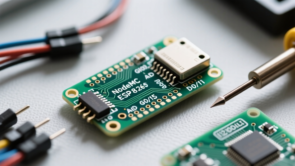
When makers first explore the NodeMCU pinout, the most common stumbling block is the discrepancy between the silkscreen labels (D0 through D8) and the actual ESP8266 GPIO (General Purpose Input/Output) numbers. The NodeMCU development board was designed to mimic the Arduino Uno's layout, which is why it uses 'D' prefixes. However, under the hood, the ESP8266 microcontroller operates strictly on GPIO numbers.
In the Arduino IDE, the NodeMCU core maps the 'D' labels to variables. For example, calling digitalWrite(D4, HIGH) works perfectly. However, if you mistakenly write digitalWrite(4, HIGH), you are not targeting D4; you are targeting GPIO4, which is physically labeled as D2 on the board. This mapping error is responsible for countless hours of debugging in maker forums. Always use the 'Dx' nomenclature or the explicit GPIOX definitions in your sketches to maintain sanity.
Quick Reference: NodeMCU V2 (Amica) & V3 (LoLin) Pin Mapping
Below is the definitive translation table for the standard 30-pin NodeMCU ESP8266 boards. This mapping applies universally to both the older Amica V2 and the wider LoLin V3 variants.
| Silkscreen Label | ESP8266 GPIO | Primary Function & Constraints |
|---|---|---|
| D0 | GPIO16 | WAKE (Deep Sleep), No PWM, No Interrupts |
| D1 | GPIO5 | Default I2C SCL, Safe for general use |
| D2 | GPIO4 | Default I2C SDA, Safe for general use |
| D3 | GPIO0 | Strapping Pin: Must be HIGH at boot (10k pull-up) |
| D4 | GPIO2 | Strapping Pin: Onboard LED, Must be HIGH at boot |
| D5 | GPIO14 | Default SPI CLK (SCK) |
| D6 | GPIO12 | Default SPI MISO |
| D7 | GPIO13 | Default SPI MOSI |
| D8 | GPIO15 | Strapping Pin: Default SPI CS, Must be LOW at boot |
| RX | GPIO3 | UART RX (Serial communication) |
| TX | GPIO1 | UART TX (Serial communication) |
| A0 | ADC0 | Analog Input (0V - 1.0V Maximum) |
FAQ: Strapping Pins and Boot Mode Failures
The ESP8266 relies on specific 'strapping pins' to determine its boot mode. If these pins are held in the wrong logic state during power-on or reset, the microcontroller will hang, enter an invalid SDIO boot mode, or wait indefinitely for a serial flash command. According to the official Espressif Hardware Design Guidelines, you must respect these internal routing requirements.
Why does my NodeMCU fail to boot when I connect a sensor to D8?
D8 (GPIO15) is a critical strapping pin that dictates the boot source. For normal SPI Flash execution (which runs your Arduino sketch), GPIO15 must be pulled LOW (0V) during boot. If you wire a relay module, an active-high sensor, or an LED directly to D8, the pin may be pulled HIGH during startup. This forces the ESP8266 into SDIO boot mode, resulting in a bricked state until the pin is released. Solution: Never use D8 for outputs that default to HIGH on startup. If you must use it for SPI Chip Select, ensure your peripheral does not pull the line high via internal resistors.
Can I use D3 and D4 for standard inputs?
D3 (GPIO0) and D4 (GPIO2) also control boot modes. GPIO0 must be HIGH to boot from flash (LOW triggers the UART bootloader for flashing new code). GPIO2 must also be HIGH or floating at boot. The NodeMCU board includes onboard pull-up resistors for these pins, making them safe for inputs like push buttons (which pull the pin LOW only when pressed). However, avoid attaching components that actively drive these pins LOW during the power-on sequence.
FAQ: Analog-to-Digital Converter (ADC) Limitations
Can I use the A0 pin to read a 5V analog sensor?
No. Unlike the Arduino Uno, which tolerates up to 5V on its analog pins, the ESP8266 ADC pin (A0) has a strict maximum voltage threshold of 1.0V. Applying 3.3V or 5V will permanently damage the internal ADC circuitry or yield saturated, inaccurate readings (stuck at 1023).
Information Gain - The Voltage Divider Framework:
To safely read a 5V sensor (like a standard potentiometer or a 5V soil moisture sensor), you must build a voltage divider. Using a 220kΩ and a 100kΩ resistor will step down 5V to approximately 1.56V, which is still too high. A safer combination is a 330kΩ and 100kΩ resistor pair, which drops 5V down to roughly 1.16V. For strict safety under 1.0V, use a 470kΩ and 100kΩ pair (yielding ~0.87V at max input). Always verify the output with a multimeter before connecting it to the NodeMCU.
Note: Some NodeMCU V3 boards include a built-in voltage divider on the A0 pin allowing up to 3.3V, but this is inconsistent across manufacturers. Always assume a 1.0V limit unless you have physically traced the PCB or verified with a multimeter.
FAQ: Sensor Wiring and Bus Defaults
What are the default I2C pins for the Wire library?
When using the Arduino Wire.h library without explicitly defining pins, the ESP8266 core defaults to:
- SDA: D2 (GPIO4)
- SCL: D1 (GPIO5)
These pins are safe from boot-mode conflicts and are the recommended standard for connecting OLED displays, BME280 sensors, and I2C multiplexers. For a deeper dive into ESP8266 I2C implementations, refer to the Random Nerd Tutorials NodeMCU Guide.
How do I wire an SPI display (like the ILI9341)?
The hardware SPI bus offers significantly faster data transfer rates than software SPI. The default HSPI pins on the NodeMCU are:
- MOSI (SD1): D7 (GPIO13)
- MISO (SD0): D6 (GPIO12)
- CLK (SCK): D5 (GPIO14)
- CS (SS): D8 (GPIO15) - Warning: Strapping Pin!
Pro-Tip: Because D8 is a strapping pin, using it as a Chip Select (CS) line for an SPI display can cause boot failures if the display module has internal pull-up resistors. To bypass this, initialize your SPI display using a 'safe' GPIO for the CS pin, such as D2 or D4, while keeping the CLK, MOSI, and MISO on their dedicated hardware SPI pins.
Deep Sleep and the D0 (GPIO16) Quirk
The ESP8266 is famous for its ultra-low power deep sleep mode, drawing roughly 20µA. However, waking up from deep sleep requires a specific hardware connection that trips up many beginners.
Rule of Thumb: To use the
ESP.deepSleep()function, you must physically wire D0 (GPIO16) to the RST pin on the NodeMCU board. Without this jumper wire, the microcontroller will go to sleep but will never wake up, requiring a manual press of the EN/RST button.
Note that GPIO16 does not support PWM or pin-change interrupts. It is strictly a real-time clock (RTC) wake signal pin.
Power Delivery: 5V, 3.3V, and the AMS1117 Regulator
Understanding the power pins is just as critical as understanding the data pins. The NodeMCU features three primary power access points:
- VIN / 5V: Connected directly to the USB 5V line. Use this to power 5V peripherals (like WS2812B LED strips) but be mindful of your USB cable's current limit (usually 500mA).
- 3V3: The output of the onboard AMS1117-3.3 voltage regulator. While the AMS1117 is rated for 800mA, the PCB traces and the USB power path often bottleneck this. Plan for a maximum continuous draw of 400mA from the 3V3 pin to prevent overheating the regulator.
- GND: There are multiple ground pins scattered across the board. They are all tied to the same common ground plane; use whichever is most convenient for your breadboard layout.
ESP8266 vs. ESP32 NodeMCU: Quick Pinout Differences
As makers migrate to the ESP32, it is vital to recognize that the ESP32 NodeMCU pinout is fundamentally different, despite sharing a similar physical footprint.
- ADC Resolution & Voltage: The ESP32 features a 12-bit ADC (0-4095) that natively reads up to 3.3V. No voltage divider is needed for 3.3V sensors.
- Strapping Pins: The ESP32 has different strapping requirements (e.g., GPIO12 must be LOW to boot at 3.3V flash voltage). However, it is generally more forgiving than the ESP8266 regarding boot hangs.
- Capacitive Touch: The ESP32 includes dedicated touch-sensitive GPIOs, eliminating the need for external capacitive sensors like the TTP223.
For comprehensive IDE configurations and board manager setups for both architectures, always consult the official ESP8266 Community GitHub Repository and the Espressif Arduino Core documentation. Mastering the NodeMCU pinout is the first step toward building robust, crash-free IoT prototypes.