
The Anatomy of ESP8266 Boot Sequences and Fatal Exceptions
When developing IoT projects, the node mcu esp8266 is a staple workhorse. However, its low-level architecture and aggressive power management frequently result in cryptic serial monitor outputs that stall development. Understanding the ESP8266 boot sequence is the first step in error diagnosis. Upon power-up or reset, the internal ROM bootloader executes, reads the GPIO pin states to determine the boot mode, and then hands control over to the flash bootloader. If your hardware connections or memory states are misaligned, the chip will either hang silently or dump a fatal exception trace.
One of the most common hurdles makers face is interpreting the hardware reset causes and software exceptions. The serial monitor often outputs a string like ets Jan 8 2013,rst cause:4, boot mode:(3,6). The rst cause value is critical for diagnosis:
- rst cause:1 - Normal power-on reset.
- rst cause:2 - External hardware reset (via the EN/RST pin).
- rst cause:4 - Hardware Watchdog Timer (WDT) timeout.
Following the boot mode, you may encounter software exceptions. According to the official ESP8266 Arduino Core documentation, these exceptions map directly to specific memory or instruction violations.
Common Node MCU ESP8266 Exception Codes
| Exception Code | Name | Common Trigger in Arduino IDE | Diagnostic Fix |
|---|---|---|---|
| 0 | IllegalInstruction | Corrupted flash memory or misaligned function pointers. | Erase entire flash using esptool; recompile with clean build. |
| 9 | LoadStoreAlignment | Attempting to read a 32-bit integer from an unaligned memory address. | Use memcpy instead of direct pointer casting for byte arrays. |
| 28 | LoadProhibited | Null pointer dereference, often from uninitialized WiFiClient objects. | Verify object instantiation before calling methods; check heap limits. |
| 29 | StoreProhibited | Writing to read-only memory or an out-of-bounds array index. | Audit array bounds; ensure String operations aren't overflowing buffers. |
Diagnosing 'Failed to Connect: Timed Out' Upload Errors
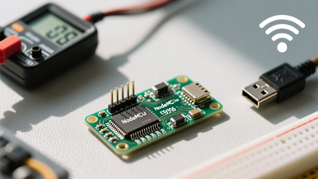
The dreaded FatalError: Failed to connect to ESP8266: Timed out waiting for packet header is the most frequent point of failure for beginners. This error indicates that the host PC cannot force the ESP8266 into UART bootloader mode. The node mcu esp8266 development boards utilize an auto-reset circuit involving the DTR and RTS lines of the USB-to-UART bridge to pull GPIO0 low (boot mode) and toggle the EN pin (reset). However, this circuit is highly dependent on the specific USB chip used on your board.
CP2102 vs. CH340G Driver Quirks
Boards equipped with the CP2102 silicon generally handle the DTR/RTS timing flawlessly on Windows and Linux. Conversely, clone boards utilizing the CH340G chip often suffer from timing skews in their Windows 11 drivers, causing the auto-reset sequence to miss the narrow bootloader window. If you are using a CH340G-based NodeMCU and facing upload timeouts, you have two reliable workarounds:
- Manual Boot Mode Entry: Press and hold the
BOOTbutton (which physically bridges GPIO0 to GND), tap theRSTbutton once, release theRSTbutton, and then release theBOOTbutton just as the Arduino IDE finishes compiling and begins the upload phase. - Driver Rollback: Uninstall the CH340 driver and install an older, community-trusted version (specifically version 3.4.2014.8) which handles the RTS handshake timing more accurately.
Resolving Power Brownouts and Wi-Fi Calibration Crashes
A subtle but destructive error manifests as random reboots exactly when the ESP8266 attempts to connect to a Wi-Fi network or transmit data. The serial monitor will show a reboot loop with rst cause:4 or simply cut off during the rf_cal[0] != initialization phase. This is almost exclusively a power brownout issue.
When the ESP-12E/F module on the NodeMCU activates its RF transmitter, current draw spikes from a resting ~20mA to over 400mA in microseconds. Most budget-friendly node mcu esp8266 clone boards utilize a generic AMS1117-3.3 linear voltage regulator. While theoretically rated for 800mA, these SOT-223 packages lack adequate thermal dissipation on small PCB ground planes, causing the output voltage to sag below the 2.9V minimum required by the ESP8266 during RF bursts.
Expert Hardware Fix: To stabilize the power rail, solder a 470µF electrolytic capacitor and a 0.1µF ceramic capacitor in parallel directly across the 3V3 and GND pins on the NodeMCU header. The electrolytic handles the bulk transient current demand, while the ceramic capacitor suppresses high-frequency RF noise, effectively eliminating Wi-Fi calibration crashes.
Watchdog Timer (WDT) Resets and Heap Fragmentation
The ESP8266 runs a background RTOS that manages Wi-Fi stacks and TCP/IP operations. If your Arduino loop() function executes a blocking operation that takes longer than 3.2 seconds without yielding control back to the system, the hardware Watchdog Timer (WDT) will forcefully reset the chip to prevent a total system lockup. This results in the wdt reset serial output.
Common culprits include synchronous HTTP GET requests, long delay() calls, or intensive cryptographic hashing. To diagnose and prevent WDT resets:
- Implement Yielding: Replace blocking
delay(1000)with non-blockingmillis()timers. If you must use a blocking loop, insertyield();ordelay(0);inside the loop to feed the software watchdog. - Monitor Heap Memory: Heap fragmentation mimics WDT crashes by causing memory allocation failures that lead to null-pointer exceptions. Use
ESP.getFreeHeap()to log available memory. A healthy node mcu esp8266 should maintain at least 15,000 bytes of free heap during active Wi-Fi operations. If the heap steadily drops over time, you have a memory leak, often caused by failing to callclient.stop()after HTTP requests or improperly managing theStringclass.
Flash Memory Corruption and Filesystem Errors
If your sketch uploads successfully but immediately crashes upon reading configuration files, or if the Arduino IDE throws a Fatal Error: ESP8266 Not Supported during SPIFFS/LittleFS uploads, your flash memory layout is likely corrupted. This frequently occurs when switching between different flash sizes (e.g., from 4MB to 1MB) in the Arduino IDE Tools menu without wiping the previous partition table.
To perform a clean slate recovery, bypass the Arduino IDE and use the official esptool.py utility via your system's command line. Executing a full chip erase resets the bootloader flags and clears corrupted filesystem blocks:
esptool.py --port COM3 erase_flashAfter erasing, always select 'Erase Flash: All Flash Contents' in the Arduino IDE tools menu before your next upload to ensure the new partition table is written cleanly. For deep hardware specifications and pinout tolerances, always refer back to the NodeMCU DevKit hardware repository to ensure your external wiring isn't causing parasitic drain on the EN or GPIO0 pins during boot.
Final Diagnostic Checklist
Troubleshooting the ESP8266 requires a methodical approach. Always verify your USB cable is rated for data transfer (not just power), ensure your power supply can deliver at least 500mA continuously, and keep your serial monitor baud rate set to 74880 during boot to capture the native ROM bootloader messages. By understanding the underlying hardware constraints of the node mcu esp8266, you can transition from guessing to precise, engineering-level error resolution.