
The Thermal Reality: Why Your Arduino Needs a Buck Converter
When powering an Arduino project from a 12V or 24V source, relying on the onboard linear regulator (LDO) is a recipe for thermal shutdown. The math is unforgiving. Power dissipation in an LDO is calculated as P = (Vin - Vout) × Iload. If you step 12V down to 5V to draw just 500mA for a few sensors and an LCD, the LDO must dissipate 3.5W of heat. A standard TO-220 package without a massive heatsink has a thermal resistance of roughly 65°C/W, meaning the junction temperature will spike by over 225°C, instantly triggering the internal thermal protection circuit.
The solution is an arduino buck converter. By using high-frequency switching and inductive energy storage, buck modules routinely achieve 85% to 95% efficiency, turning a 3.5W heat problem into a negligible 0.3W footprint. However, not all buck modules are compatible with the sensitive analog and digital ecosystems of modern microcontrollers. This guide maps specific converter topologies to 5V and 3.3V Arduino architectures, addressing electromagnetic interference (EMI), ripple voltage, and the pervasive issue of counterfeit silicon in the maker market.
Module Comparison Matrix: The 2026 Maker Market
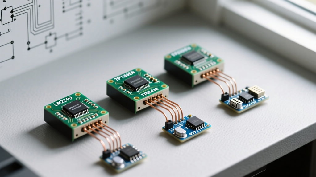
The market is flooded with step-down modules. Below is a technical breakdown of the four most common architectures you will encounter, evaluated on real-world performance rather than theoretical datasheet maximums.
| Module Core IC | Switching Freq. | Realistic Max Current | Avg. Price (2026) | Best MCU Application | Noise / Ripple Profile |
|---|---|---|---|---|---|
| LM2596 (Clone) | 150 kHz | 1.5A (Continuous) | $1.50 | Uno R3, Mega 2560 (Digital only) | High (Large ripple, low freq) |
| MP1584EN | 1.5 MHz | 2.5A (Continuous) | $2.20 | Nano 33 IoT, ESP32 Dev Kits | Medium (High freq, easier to filter) |
| XL4015 (5A rated) | 180 kHz | 3.5A (w/ heatsink) | $3.80 | Motor drivers, High-current 5V rails | High (Requires LC filtering for MCUs) |
| TPS5430 (TI Genuine) | 500 kHz | 3.0A (Continuous) | $7.50 | Precision ADC, Audio, Uno R4 Minima | Low (Excellent transient response) |
Compatibility Profiles: Matching the Converter to the MCU
Profile 1: The 5V Ecosystem (Uno R3, Mega 2560, Uno R4)
The classic ATmega328P and the modern Renesas RA4M1 (found in the Arduino Uno R4 Minima) operate natively at 5V. While the digital logic is relatively robust against minor voltage sags, the analog-to-digital converter (ADC) is highly susceptible to switching noise.
- The LM2596 Problem: The standard LM2596 clone switches at 150 kHz. This frequency and its harmonics easily alias into the Arduino's ADC sampling window, causing
analogRead()values to fluctuate by 15-30 LSBs (Least Significant Bits). If your project involves reading precision load cells or thermistors, the LM2596 is incompatible without heavy secondary filtering. - The Uno R4 Edge Case: The Uno R4 Minima features a much more sophisticated power tree and a 14-bit ADC. Feeding it noisy 5V from a cheap buck converter will severely degrade its high-resolution analog capabilities. For the R4, invest in the TPS5430 or MP1584EN modules to maintain signal integrity.
Profile 2: The 3.3V Ecosystem (Nano 33, ESP32, SAMD21)
3.3V boards have zero tolerance for overvoltage. The absolute maximum rating for the ESP32's GPIO pins and internal LDO is typically 3.6V. A spike to 4.0V will permanently brick the silicon.
Critical Warning: Never use adjustable buck converters with standard 5% tolerance feedback resistors for 3.3V rails. A 5% drift on a $1.50 module can easily push the output to 3.55V under light loads, risking the lifespan of your ESP32. Always use fixed-output 3.3V modules, or manually verify adjustable modules with a 4.5-digit multimeter before connecting them to 3.3V logic.
For 3.3V applications, the MP1584EN is the undisputed champion. Its 1.5 MHz switching frequency allows for a much smaller inductor footprint, and its transient response is fast enough to handle the sudden current spikes (up to 500mA) when an ESP32 transmits over Wi-Fi. For deeper insights into ESP32 power budgets and brownout detection, refer to Adafruit's power management guidelines.
The EMI and ADC Noise Problem: Designing an LC Filter
Buck converters generate high di/dt (rate of current change) loops, which radiate electromagnetic interference. When routing power from a buck converter to an Arduino's 5V or 3V3 pin, you must isolate the MCU's sensitive AVCC (Analog VCC) rail.
Implement this simple, low-cost LC low-pass filter directly at the Arduino header:
- Inductor: Place a 10µH to 47µH radial choke in series with the
AVCCpin. - Capacitor Bank: On the MCU side of the inductor, place a 10µF electrolytic capacitor in parallel with a 100nF (0.1µF) ceramic capacitor to ground.
- Result: This creates a second-order filter that aggressively attenuates the 150 kHz to 1.5 MHz switching ripple, dropping ADC noise floors from ~25mV down to <3mV.
Field Tuning and the 'Hot Glue' Protocol
If you must use an adjustable module (like the XL4015 or LM2596), the physical tuning process is a frequent point of failure. The blue multi-turn trimpots used on these modules are highly sensitive to vibration and thermal expansion.
Step-by-Step Thermal Tuning Guide
- Power the module with your actual input voltage (e.g., 12V) but no load.
- Connect a calibrated digital multimeter to the output terminals.
- Turn the trimpot counter-clockwise until it stops (minimum voltage).
- Slowly turn clockwise until you hit exactly 5.00V or 3.30V.
- The Thermal Drift Wait: Connect your actual MCU load. Let the module run for 15 minutes. The internal temperature rise will shift the resistance of the cheap carbon-film trimpot, often dropping the voltage by 0.1V to 0.2V.
- Re-measure and adjust while the module is hot.
- The Maker's Secret: Once tuned, apply a thick bead of high-temp hot glue or RTV silicone over the trimpot. This locks the wiper in place, preventing vibration-induced drift in mobile or robotic applications.
Failure Modes: Navigating the Clone Silicon Market
According to Texas Instruments' step-down buck topology overview, genuine switching regulators require precise internal compensation networks and robust MOSFETs. The $1.50 LM2596 modules found on bulk e-commerce sites rarely contain genuine TI silicon.
Common Failure Modes in Clone Modules:
- Undersized Die: Clones often use an LM2576 die laser-marked as an LM2596. The LM2576 switches at 52 kHz and requires a much larger inductor. When paired with the small 33µH inductor provided on the LM2596 board, the core saturates at roughly 1.2A, causing the IC to overheat and fail short-circuit, sending 12V directly into your Arduino's 5V rail and destroying it instantly.
- Missing Snubber Networks: Genuine designs include an RC snubber across the Schottky diode to dampen high-frequency ringing. Clone boards frequently omit these passives to save $0.02 per unit, resulting in massive EMI spikes that can reset your Arduino randomly via the RESET pin.
Final Verdict: Selecting Your Power Architecture
For high-current, non-analog 5V applications (like driving relay banks or stepper motor drivers alongside an Arduino Mega), the XL4015 offers the best cost-to-performance ratio. For 3.3V IoT nodes utilizing the ESP32 or Nano 33, the MP1584EN provides the necessary high-frequency switching and compact footprint. However, if your project demands precision analog readings, audio processing, or operates in mission-critical environments, bypass the clone market entirely and design a custom carrier board using a genuine TPS5430 or TPS563200 IC. Understanding the intersection of switching physics and microcontroller architecture is the hallmark of a mature embedded systems engineer.