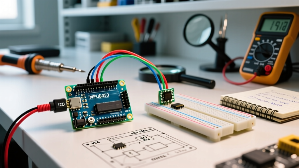

Integrating audio feedback into microcontroller projects is a fundamental skill for hardware engineers and makers. Whether you are building an IoT alarm system, a digital metronome, or a retro gaming console, the buzzer Arduino combination remains the most cost-effective and reliable method for generating alert tones and simple melodies. As we navigate through 2026, while MEMS (Micro-Electro-Mechanical Systems) speakers are becoming popular for high-fidelity voice prompts, piezoelectric buzzers remain the undisputed industry standard for high-SPL (Sound Pressure Level) alert tones due to their low power consumption and minimal footprint.
The Core Physics: Active vs. Passive Piezo Transducers
Before writing a single line of C++ code, it is critical to understand the hardware you are driving. The term 'buzzer' is often used interchangeably, but in electronics, it refers to two fundamentally different components: active buzzers and passive buzzers. Both typically utilize a piezoelectric ceramic disc (usually Lead Zirconate Titanate, or PZT) bonded to a metal substrate, but their internal driving circuitry differs entirely.
| Feature | Active Buzzer (e.g., KY-012) | Passive Buzzer (e.g., KY-006 / Murata PKM Series) |
|---|---|---|
| Internal Oscillator | Yes (Built-in CMOS driving circuit) | No (Raw piezoelectric element) |
| Signal Requirement | DC Voltage (HIGH/LOW) | AC Square Wave (PWM / Oscillating Signal) |
| Frequency Control | Fixed (Determined by internal circuit) | Variable (Controlled via MCU code) |
| Average Cost (2026) | ~$0.30 per unit (bulk) | ~$0.15 - $0.45 per unit (bulk) |
| Best Use Case | Simple alarms, status beeps | Melodies, variable pitch sirens, UI feedback |
Hardware Design: Driving a Buzzer Arduino Circuit Safely
A common and destructive mistake made by beginners is wiring a piezo buzzer directly between an ATmega328P GPIO pin and GND. While a piezo buzzer is fundamentally a capacitive load rather than a purely resistive one, it can draw dangerous current spikes that degrade or destroy the microcontroller's silicon over time.
The GPIO Current Trap (and the Math Behind It)
The ATmega328P datasheet specifies an absolute maximum DC current of 40mA per I/O pin, with a recommended operating limit of 20mA. A typical 12mm piezo transducer has a capacitance of approximately 15nF. When you output a 5V square wave at 4kHz, the rapid voltage transitions ($dv/dt$) cause instantaneous current spikes. Using the formula $I = C \times (dV/dt)$, a 5V step occurring in 1 microsecond results in a transient spike of 75mA. This nearly doubles the absolute maximum rating of the pin.
The Transistor Switching Solution
To protect your MCU, you must use an external switching transistor. An NPN BJT like the BC547 or 2N2222 is ideal for this application.
- Base Resistor: Connect a 1kΩ resistor between the Arduino PWM pin and the base of the transistor to limit base current to ~4.3mA.
- Collector: Connect to the negative terminal of the buzzer.
- Emitter: Connect to system GND.
- Flyback Diode: Wire a 1N4148 signal diode in reverse bias (cathode to VCC, anode to collector) across the buzzer terminals. This clamps inductive/capacitive kickback and prevents voltage spikes from frying the transistor.
Pro-Tip for 2026 IoT Designs: If you are designing a custom PCB and space is at a premium, replace the through-hole BC547 with an N-channel MOSFET like the BSS138. It requires virtually zero steady-state gate current, making it perfect for battery-operated, low-power sensor nodes.
Software Architecture: Mastering the tone() Function
For passive buzzers, the Arduino IDE provides the built-in tone(pin, frequency, duration) function. Under the hood, on the ATmega328P, this function hijacks Timer2 to generate a 50% duty-cycle square wave at the requested frequency. According to the official Arduino tone() reference, the function can generate frequencies from 31Hz up to 65535Hz, though human hearing caps at roughly 20kHz.
Timer Conflicts and PWM Limitations
Because tone() relies on Timer2, it inherently conflicts with hardware PWM on pins controlled by that same timer. On the Arduino Uno (ATmega328P), Timer2 controls PWM on Pins 3 and 11. If you call tone(), analogWrite() on pins 3 and 11 will cease to function correctly until noTone() is called. If your project requires simultaneous motor speed control (PWM) and audio generation, you must use the TimerOne or TimerThree libraries to shift the audio generation to a different hardware timer.
Code Implementation: Generating a Siren Sweep
Below is a highly optimized C++ snippet for generating a police-style siren sweep using a passive buzzer. This code assumes the buzzer is driven via a transistor on Pin 9.
const int buzzerPin = 9;
const int minFreq = 2000;
const int maxFreq = 4000;
const int sweepDelay = 10; // ms per step

void setup() {
  pinMode(buzzerPin, OUTPUT);
}

void loop() {
  // Sweep Up
  for(int freq = minFreq; freq <= maxFreq; freq += 50) {
    tone(buzzerPin, freq, sweepDelay);
    delay(sweepDelay);
  }

  // Sweep Down
  for(int freq = maxFreq; freq >= minFreq; freq -= 50) {
    tone(buzzerPin, freq, sweepDelay);
    delay(sweepDelay);
  }

  // Pause between sirens
  noTone(buzzerPin);
  delay(1500);
}
Acoustic Engineering: Resonance and SPL Optimization
The most frequent complaint among makers is that their passive buzzer sounds 'weak' or 'quiet,' even when the code is correct. This is almost always an issue of resonant frequency mismatch. Piezoelectric transducers are highly resonant mechanical devices. As detailed in Murata's piezoelectric component guides, a buzzer will only produce its rated SPL (often 85dB to 95dB at 10cm) when driven at its specific resonant frequency ($f_0$).
For example, the popular Murata PKM13EPYH4002-A0 has a resonant frequency of 4.0 kHz. If you use the tone() function to play a 440 Hz (A4) musical note through this component, the acoustic output will drop by 15 to 20 decibels, sounding like a faint click rather than a clear tone. Always check the manufacturer datasheet for the $f_0$ parameter and design your alert melodies to hover near that specific frequency band for maximum acoustic efficiency.
Helmholtz Cavity Design
To amplify lower frequencies, acoustic engineers mount the piezo element over a sealed or ported cavity, creating a Helmholtz resonator. If you are 3D printing an enclosure for your Arduino Tone Melody project, adding a precisely calculated rear-chamber volume (typically between 1.5cm³ and 3.0cm³ for 12mm discs) and a front-facing acoustic port can boost low-mid frequency SPL by up to 8dB.
Troubleshooting Common Buzzer Arduino Failures
When your circuit fails to produce the expected audio, use this diagnostic matrix to identify the root cause:
| Symptom | Probable Cause | Engineering Fix |
|---|---|---|
| Faint clicking, no continuous tone | Using an Active Buzzer with PWM / tone() function. |
Switch to digitalWrite(HIGH/LOW) or replace with a Passive Buzzer. |
| Extremely quiet / muffled output | Driving a Passive Buzzer far below its mechanical resonant frequency. | Consult datasheet for $f_0$ and adjust software frequency to match. |
| MCU resets randomly during loud tones | Brownout due to current draw, or back-EMF spike causing logic latch-up. | Install a 1N4148 flyback diode and ensure a 100µF decoupling capacitor on the VCC rail. |
| 'Ghost' buzzing when MCU is idle | EMI (Electromagnetic Interference) from long, unshielded wires acting as antennas. | Add a 10kΩ pull-down resistor between the transistor base and GND to keep it firmly off. |
| PWM motor stutters when tone plays | tone() function overriding Timer2, affecting Pins 3 & 11. |
Move motor PWM to Pins 5 or 6 (Timer0/Timer1) or use the TimerOne library. |
Conclusion
Mastering the buzzer Arduino ecosystem requires moving beyond simple copy-paste tutorials and understanding the intersection of hardware physics and software timers. By properly buffering your GPIO pins with a transistor, respecting the mechanical resonant frequencies of PZT ceramics, and managing ATmega timer conflicts, you can engineer robust, high-decibel audio feedback systems that will reliably operate in the field for years to come.