
The "Goldilocks" Zone: Why 10kΩ is the Arduino Standard
When designing a user interface for a microcontroller project—whether you are building a DIY synthesizer, a motor speed controller, or a simple servo tester—the rotary knob is a staple component. However, standing in the components aisle or browsing an online distributor like Mouser or Digi-Key, you will face a critical decision: what resistance should you choose? The standard answer echoed across maker forums is almost always 10kΩ. But why is this specific potentiometer value for Arduino circuits so universally recommended, and what happens if you deviate from it?
As of 2026, while newer 32-bit ARM and RISC-V boards like the ESP32-S3 or Arduino Nano RP2040 Connect offer advanced analog-to-digital converters (ADCs), the classic 8-bit AVR architecture (ATmega328P and ATmega2560) found in the Uno, Nano, and Mega remains the baseline for analog input design. Understanding the physics of the ADC on these legacy boards is the key to selecting the perfect resistance for your voltage divider.
Understanding the ATmega SAR ADC Architecture
The Arduino Uno utilizes a Successive Approximation Register (SAR) ADC. Unlike a simple voltmeter that continuously measures voltage, a SAR ADC takes discrete "samples" of the incoming voltage. Inside the microcontroller, the analog pin is connected to a multiplexer, which routes the signal to a tiny internal sample-and-hold (S/H) capacitor (typically around 14pF) through a series of internal MOSFET switches that introduce about 100Ω to 200Ω of resistance.
When the ADC triggers a read, it closes the switch, allowing the external voltage to charge the internal 14pF capacitor. This charging process is governed by the RC time constant. If your external potentiometer has too high a resistance, the capacitor cannot charge to the correct voltage within the ADC's sampling window (usually a few microseconds). The result is an artificially low, fluctuating, or entirely inaccurate reading. According to the official Microchip/Atmel datasheet for the ATmega328P, the recommended maximum impedance for the analog signal source is 10kΩ. This ensures the internal capacitor charges fully and accurately before the conversion begins.
Resistance Comparison Matrix: Low vs. Medium vs. High
To visualize how different potentiometer values impact your circuit, we must balance current consumption, ADC accuracy, and noise susceptibility. Below is a comparison matrix for a standard 5V Arduino system.
| Pot Value | Current Draw (at 5V) | ADC Accuracy | Noise Susceptibility | Best Use Case |
|---|---|---|---|---|
| 1kΩ | 5.0 mA | Excellent | Very Low | Battery-powered devices where fast ADC settling is critical, but wastes power. |
| 10kΩ | 0.5 mA | Excellent | Low | The universal standard for 5V and 3.3V Arduino analog inputs. |
| 100kΩ | 0.05 mA | Poor (Unstable) | High | Ultra-low power sleep-mode circuits (requires external buffer op-amp). |
| 1MΩ | 0.005 mA | Failure | Extreme | Not recommended for direct Arduino ADC connection under any circumstances. |
While a 1kΩ pot offers fantastic signal integrity, it draws 5mA of continuous current just to sit idle. In a battery-operated IoT sensor node, this parasitic drain will kill a CR2032 coin cell in days. The 10kΩ value draws a negligible 0.5mA, preserving battery life while keeping the impedance well below the 10kΩ threshold required by the AVR ADC.
Real-World Failure Modes and Edge Cases
Theoretical datasheets only tell half the story. In practical bench testing, choosing the wrong potentiometer value for Arduino projects introduces several insidious hardware bugs.
1. Analog Pin Crosstalk (Ghosting)
Imagine you have two 100kΩ potentiometers connected to pins A0 and A1. You write a sketch to read A0, then immediately read A1. You notice that turning the knob on A0 slightly changes the reading on A1, even though the physical knob on A1 hasn't moved. This is analog crosstalk.
Because the 100kΩ resistance restricts current flow, the internal S/H capacitor retains the voltage from A0 when the multiplexer switches to A1. The capacitor doesn't have enough time to bleed off and recharge to A1's voltage. To fix this without changing the hardware, makers often insert a "dummy read" or a 10-microsecond delay() between analogRead() calls. However, the proper hardware solution is to simply use 10kΩ pots, or add a 100nF ceramic capacitor between the wiper pin and ground to act as an external charge reservoir. For a deeper dive into how voltage dividers interact with microcontroller pins, refer to this comprehensive guide on voltage dividers and loading effects by SparkFun.
2. Mechanical Wear and Track Material
The resistance value isn't the only spec that matters; the physical construction of the resistive track dictates the lifespan of your interface. As of 2026, component pricing remains highly stratified based on track material:
- Carbon Track (e.g., Bourns PTV09A series, ~$0.45): Cheap and ubiquitous. However, the carbon paste wears down over thousands of rotations, creating "dead spots" and increasing the wiper contact resistance. This manifests as sudden jumps in your serial monitor output.
- Cermet Track (e.g., Bourns 3296W multi-turn, ~$3.50): Made from ceramic and metal alloy. Highly stable, resistant to temperature drift, and rated for hundreds of thousands of cycles. Ideal for precision calibration dials.
- Conductive Plastic (e.g., ALPS RK09K series, ~$1.20): The gold standard for audio mixing boards and high-end UI knobs. Extremely smooth resolution and long life.
Pro-Tip: If your serial monitor shows erratic jumps (e.g., leaping from 450 to 890 and back) when you slowly turn a cheap carbon potentiometer, the wiper is bouncing over microscopic pits in the carbon track. Software debouncing or an Exponential Moving Average (EMA) filter in your C++ sketch is mandatory to smooth out these mechanical hardware flaws.
Wiring Topologies: Voltage Divider vs. Rheostat
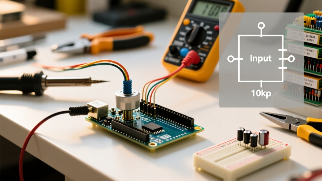
A common beginner mistake when experimenting with a new potentiometer value for Arduino analog inputs is wiring the component as a variable resistor (rheostat) using only two pins, rather than a voltage divider using all three.
If you connect only the wiper and one outer leg to 5V, and leave the third leg floating, you are relying on the Arduino's internal pull-up resistors or floating impedance to complete the circuit. This results in non-linear, highly erratic readings that drift with ambient humidity and electromagnetic interference (EMI). You must always wire the potentiometer as a 3-pin voltage divider:
- Pin 1 (Left): Connect to 5V (or 3.3V, matching your board's logic level).
- Pin 2 (Wiper/Center): Connect to the Arduino Analog Input (e.g., A0).
- Pin 3 (Right): Connect to GND.
This topology ensures a ratiometric measurement. The ADC reads the ratio of the voltage drop, meaning if your 5V USB supply sags to 4.7V due to a heavy motor load, the analog reading remains perfectly accurate relative to the supply. The official Arduino documentation outlines this exact setup in their AnalogReadSerial built-in example, which remains the foundational starting point for analog sensor integration.
Software Mitigation for Hardware Imperfections
Even when you select the mathematically perfect 10kΩ cermet potentiometer, the Arduino's ADC will still exhibit ±2 LSB (Least Significant Bit) of inherent noise. A perfectly still knob might output 512, 513, 511, 512 in rapid succession.
Before you attempt to map these values using the map() function to control a PWM pin or a servo, you must stabilize the data stream. While hardware capacitors (a 0.1µF ceramic cap at the wiper) filter high-frequency EMI, software filtering handles low-frequency drift. Implementing a simple rolling average array or an IIR (Infinite Impulse Response) low-pass filter in your sketch will transform a jittery hardware signal into a buttery-smooth user input. For more advanced techniques on converting raw ADC integers into stable physical voltage readings, explore the ReadAnalogVoltage tutorial in the Arduino language reference.
Summary
Selecting the correct potentiometer value for Arduino circuits is an exercise in balancing electrical physics with practical hardware limitations. Stick to the 10kΩ standard to satisfy the ATmega SAR ADC's impedance requirements, avoid the ghosting pitfalls of high-resistance pots, and prevent the parasitic battery drain of low-resistance alternatives. Pair your 10kΩ component with a proper 3-pin voltage divider wiring topology and a basic software smoothing algorithm, and you will achieve professional-grade, noise-free analog control for your 2026 maker projects.