
The 2026 Landscape: Navigating the Models of Arduino
The era of relying solely on the classic ATmega328P for complex maker projects is long behind us. As we move through 2026, the ecosystem of microcontrollers has fractured into highly specialized architectures. When evaluating different models of Arduino for advanced IoT deployments, robotic actuation, or edge AI, engineers must look beyond basic pinouts. Modern configurations demand a deep understanding of heterogeneous multi-core processors, network coprocessors, and specific IDE board manager dependencies.
This configuration guide dissects the technical setup, IDE integration, and hardware edge cases for the most capable boards in the current lineup. Whether you are building a low-power LoRaWAN sensor node or a dual-core robotic vision system, selecting and configuring the right hardware is the critical first step.
Configuration Pro-Tip: Always use the latest Arduino IDE 2.x release. The legacy 1.8.x branch lacks the integrated Serial Plotter and advanced debugging probes required for the newer ARM Cortex and ESP32-S3 architectures found in modern boards.
Technical Comparison Matrix: Specs, Pricing, and Use Cases
Before diving into software configuration, it is essential to map your project requirements to the silicon capabilities. The table below outlines the primary specifications and 2026 retail pricing for four dominant architectures.
| Model | Primary MCU / Architecture | Flash / SRAM | Est. Price (USD) | Ideal Configuration Scenario |
|---|---|---|---|---|
| Arduino Nano ESP32 | ESP32-S3 (Dual-core LX7) | 8MB / 512KB | $21.00 | High-throughput WiFi/BLE IoT nodes, capacitive touch interfaces. |
| Arduino Uno R4 WiFi | Renesas RA4M1 + ESP32-S3 | 256KB / 32KB | $27.50 | 5V tolerant legacy shield integration with modern cloud telemetry. |
| Arduino Portenta H7 | STM32H747 (Cortex-M7/M4) | 2MB / 1MB | $115.00 | Edge AI, machine vision, and real-time robotic motor control. |
| Arduino MKR WAN 1310 | SAMD21 + Murata CMWX1ZZABZ | 256KB / 32KB | $35.00 | Off-grid, ultra-low-power LoRaWAN agricultural or environmental sensing. |
Step-by-Step IDE Configuration for Advanced Boards
Unlike the plug-and-play nature of the classic Uno R3, modern models of Arduino require precise Board Manager configurations. Missing a core dependency or selecting the wrong partition scheme will result in silent compilation failures or boot loops.
Configuring the Arduino Nano ESP32
The Nano ESP32 utilizes the powerful ESP32-S3 chip. While Arduino provides a proprietary core for it, many advanced users prefer the official Espressif core for access to specific BLE and WiFi mesh features. To configure the Espressif core:
- Navigate to File > Preferences in the Arduino IDE.
- In the 'Additional Boards Manager URLs' field, paste the official Espressif JSON link:
https://raw.githubusercontent.com/espressif/arduino-esp32/gh-pages/package_esp32_index.json. For more details on core management, refer to the Arduino IDE Board Manager documentation. - Open the Board Manager, search for
esp32, and install the latest 3.x release. - Critical Edge Case: The Nano ESP32 features a unique GPIO mapping quirk. The physical pin labeled
D2on the silkscreen actually maps toGPIO48on the ESP32-S3 silicon. Always use the 'Arduino Nano ESP32' board definition in the IDE to ensure the software abstraction layer correctly translates legacy Arduino pin calls to the native ESP32 GPIO matrix.
Setting up the Portenta H7 for Dual-Core Edge AI
The Portenta H7 is a beast of a board, featuring an STM32H747XI dual-core microcontroller. The Cortex-M7 runs at 480 MHz, while the Cortex-M4 runs at 240 MHz. Configuring this board requires splitting your workload.
- M7 Core Configuration: Use this for heavy computational tasks, such as running TensorFlow Lite for Microcontrollers (TFLM) inference on camera data.
- M4 Core Configuration: Delegate real-time, deterministic tasks here, such as reading quadrature encoders or generating precise PWM signals for BLDC motor controllers.
To compile for both cores simultaneously, you must install the Arduino Mbed OS Portenta Boards core. In your code, use preprocessor directives to separate the logic:
#ifdef CORE_CM7
  // Code for the M7 Core (Vision and AI)
#endif

#ifdef CORE_CM4
  // Code for the M4 Core (Motor Control)
#endif
Note: Inter-core communication requires configuring the OpenAMP library to establish an RPMsg (Remote Processor Messaging) RPC channel between the M7 and M4 cores.
Hardware Configuration: Power and Pinout Edge Cases
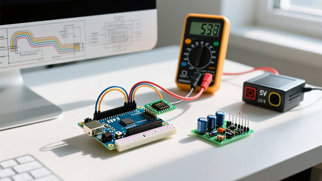
Software configuration is only half the battle. The physical integration of these models of Arduino into custom PCBs or breadboards introduces distinct electrical engineering challenges.
Logic Level Translation and I2C Capacitance
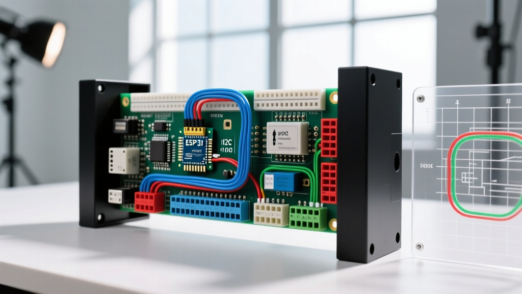
A frequent failure mode in mixed-signal projects involves I2C bus lockups. The Arduino Uno R4 WiFi operates its primary Renesas MCU at 5V logic, but the onboard ESP32-S3 network coprocessor operates strictly at 3.3V. While the board handles internal level shifting, external I2C sensors connected to the main header require careful pull-up resistor configuration.
- 5V Sensors: Use 4.7kΩ pull-up resistors tied to the 5V rail.
- 3.3V Sensors: If connecting a 3.3V sensor (like a BME280) to a 5V-tolerant board like the Uno R4, you must use a bidirectional logic level shifter (e.g., NXP PCA9306) or tie the pull-ups to the 3.3V out pin and rely on the internal protection diodes of the Renesas chip, though the latter is not recommended for high-speed (400kHz) I2C.
- Bus Capacitance: Keep I2C trace lengths under 30cm. If your wiring exceeds this, reduce the I2C clock speed to 100kHz via
Wire.setClock(100000);to prevent signal degradation.
Power Delivery and Brown-Out Resets
When configuring the Arduino Nano ESP32 for high-power WiFi transmission, the board can draw peak currents exceeding 350mA. If you are powering the board via the 5V pin from an external linear regulator (like an L7805), the voltage drop under load can trigger the ESP32's internal brown-out detector (BOD), causing a continuous reset loop. Always configure your power supply to deliver at least 500mA with low ESR decoupling capacitors (100µF tantalum + 100nF ceramic) placed within 5mm of the board's VIN pin.
Troubleshooting Common Board Manager and Upload Failures
Even with perfect hardware configuration, firmware uploads can fail due to bootloader state issues.
DFU Mode and Bootloader Recovery
If your Arduino Portenta H7 or Nano ESP32 becomes unresponsive and the IDE throws a 'No device found on port' error, the bootloader may be corrupted or stuck. You can force the board into Device Firmware Upgrade (DFU) mode by executing the 'double-tap' reset sequence:
- Press and release the reset button quickly.
- Immediately press and release it a second time.
- The onboard LED should pulse rhythmically (usually green or purple), indicating the ROM bootloader is active and waiting for a USB DFU connection.
- Select the newly created DFU COM port in the IDE and re-upload your sketch.
For deeper insights into ESP32 bootloader recovery and strapping pin configurations, the Espressif Arduino Core repository on GitHub provides exhaustive troubleshooting matrices for hardware strap pin conflicts.
Frequently Asked Questions (FAQ)
Can I use standard Arduino shields with the Portenta H7?
No. The Portenta H7 utilizes the high-density 80-pin Arduino Pro form factor, not the classic Uno R3 footprint. To use standard shields, you must configure a Portenta Breakout Board or use the specific Arduino Pro shields designed for the high-speed MIPI and PCIe interfaces native to the Portenta ecosystem. You can view the official hardware compatibility lists on the Arduino Store.
Which model is best for battery-powered outdoor deployments?
For off-grid deployments, the MKR WAN 1310 is the superior choice. By configuring the SAMD21 to enter deep sleep modes via the ArduinoLowPower library, and utilizing the LoRaWAN stack to transmit small payloads every 15 minutes, you can achieve a battery life of 1 to 2 years on a standard 2000mAh LiPo battery.
How do I update the ESP32-S3 bridge firmware on the Uno R4 WiFi?
The Uno R4 WiFi uses the ESP32-S3 as a network bridge. If you experience TLS handshake failures with modern cloud providers, you likely need to update the bridge firmware. Open the IDE, navigate to File > Examples > WiFiS3 > Tools > WiFiFirmwareUpdater, upload the sketch, and follow the Serial Monitor prompts to flash the latest AT-command firmware to the coprocessor.