
The Physics of Photoplethysmography (PPG) in DIY Biometrics
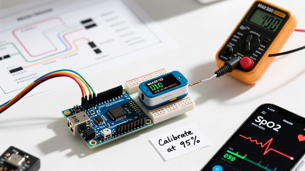
Building an Arduino pulse ox monitor is a premier project for makers diving into biometric signal processing. Unlike simple temperature or humidity sensors, a pulse oximeter relies on photoplethysmography (PPG)—the optical measurement of blood volume changes in the microvascular bed of tissue. By shining red (660nm) and infrared (880nm) light through a fingertip and measuring the absorption rates, we can calculate both heart rate (BPM) and peripheral oxygen saturation (SpO2).
Oxygenated hemoglobin absorbs more infrared light and allows more red light to pass through. Deoxygenated hemoglobin does the exact opposite. By analyzing the AC (pulsatile arterial blood) and DC (static tissue, venous blood) components of these two wavelengths, the Arduino can compute the SpO2 percentage. However, translating raw photon counts into medical-grade data requires precise hardware configuration and robust digital filtering.
Hardware Selection: MAX30102 vs. MAX30105
The undisputed standard for DIY pulse oximetry is the Maxim Integrated (now Analog Devices) MAX30102 sensor. However, as of 2026, the maker market is flooded with inexpensive clone boards that present severe integration challenges. Furthermore, the MAX30105 is often a superior choice for 5V Arduino ecosystems.
Expert Warning: The MAX30102 is strictly a 1.8V internal logic device with a maximum absolute rating of 3.6V on the I2C lines. Connecting a bare MAX30102 breakout directly to a 5V Arduino Uno's SDA/SCL pins will permanently fry the sensor's I2C transceiver within milliseconds. The MAX30105, while technically designed for particle sensing, includes the same SpO2 optical engine but features an onboard 3.3V LDO voltage regulator and 5V-tolerant I2C level shifters.
Component BOM and 2026 Pricing
| Component | Model / Variant | Approx. Price | Notes |
|---|---|---|---|
| Microcontroller | Arduino Nano 33 IoT | $22.00 | Native 3.3V logic, ideal for raw MAX30102 |
| Microcontroller | Arduino Uno R3 / R4 | $15.00 - $27.50 | Requires MAX30105 or external logic level shifter |
| Optical Sensor | SparkFun MAX30105 | $29.95 | Genuine, 5V safe, includes pull-ups |
| Optical Sensor | Generic MAX30102 Clone | $3.50 - $6.00 | High failure rate, missing LDOs, requires 3.3V MCU |
| Passives | 4.7kΩ Pull-up Resistors | $0.10 | Required if clone board lacks I2C pull-ups |
Wiring and the 3.3V Logic Trap
Communication with the sensor is handled via the I2C protocol. The Arduino Wire library abstracts this, but physical layer voltage mismatches remain the number one cause of I2C lockups in biometric builds.
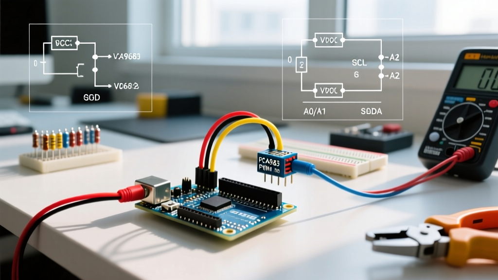
Pinout Matrix for Arduino Nano 33 IoT (3.3V Native)
| MAX30102 Pin | Arduino Nano 33 IoT Pin | Function & Configuration |
|---|---|---|
| VIN / VCC | 3.3V | Power supply. Do NOT use 5V on raw clone boards. |
| GND | GND | Common ground reference. |
| SDA | A4 (SDA) | I2C Data. Ensure 4.7kΩ pull-up to 3.3V if missing. |
| SCL | A5 (SCL) | I2C Clock. |
| INT | D2 | Interrupt pin. Active LOW. Triggers when FIFO fills. |
Step-by-Step Firmware Configuration
To process the high-speed optical data, we rely on the sensor's internal 32-deep FIFO buffer. If the Arduino does not read this buffer fast enough, it overflows, resulting in dropped beats and skewed SpO2 calculations.
- Library Installation: Install the SparkFun MAX3010x Sensor Library via the Arduino Library Manager. It provides optimized FIFO parsing and interrupt handling.
- Hardware Initialization: Call
particleSensor.begin(Wire, I2C_SPEED_FAST). The default I2C speed is 100kHz, but bumping to 400kHz (Fast Mode) is highly recommended to clear the FIFO before the next sample arrives. - LED Pulse Amplitude: This is the most critical calibration step. The IR and Red LED currents must be tuned to your specific finger tissue density. Setting them to maximum (50mA) causes sensor saturation (clipping), while setting them too low yields a poor signal-to-noise ratio (SNR). Start with an amplitude of
0x2F(approx. 7.6mA) and adjust based on the Serial Plotter baseline.
Optimal Initialization Parameters
According to the Analog Devices MAX30102 datasheet, configuring the sample rate and pulse width dictates the resolution and power draw. For a balanced Arduino pulse ox build, use these parameters:
- LED Pulse Amplitude:
0x2F(Red),0x2F(IR) - Sample Rate:
100 SPS(Samples Per Second) - Sufficient for BPM, reduces processing overhead on 8-bit MCUs. - Pulse Width:
411 µs- Provides 18-bit ADC resolution, maximizing the dynamic range for detecting subtle AC variations. - ADC Range:
4096- Prevents clipping when the finger is pressed firmly against the sensor.
Calculating SpO2: The R-Value Algorithm
Raw PPG data is incredibly noisy. Ambient light, micro-movements, and venous blood pulsation all corrupt the signal. The SparkFun Hookup Guide outlines the necessity of applying a 4-point moving average filter to smooth the raw FIFO data before peak detection.
Once the AC and DC components are isolated for both Red and IR wavelengths, the Arduino calculates the 'R' value:
R = (AC_red / DC_red) / (AC_ir / DC_ir)
Because the exact mathematical mapping of 'R' to SpO2 is proprietary and empirically derived through clinical blood-gas analysis, makers use a polynomial approximation lookup table. An R-value of ~0.5 typically correlates to 100% SpO2, while an R-value of ~1.0 correlates to roughly 85% SpO2. You must implement a linear interpolation function in your sketch to map the calculated R-value against these empirical boundary points.
Real-World Troubleshooting & Edge Cases
When moving from the workbench to real-world testing, your Arduino pulse ox will encounter several physical edge cases that code alone cannot fix.
1. Motion Artifacts and Baseline Wander
If the user's hand shakes, the low-frequency noise (baseline wander) will dwarf the 1Hz-2Hz pulsatile signal. Fix: Implement a digital bandpass filter in your Arduino sketch, allowing only frequencies between 0.5Hz (30 BPM) and 3.5Hz (210 BPM) to pass. Alternatively, use an accelerometer (like the onboard LSM6DS3 on the Nano 33 IoT) to gate the PPG readings, pausing SpO2 calculation when motion exceeds a set threshold.
2. Finger Pressure and Venous Pooling
Pressing the finger too hard against the MAX30102 glass compresses the capillaries and restricts arterial flow, flattening the AC waveform and causing the SpO2 algorithm to output erratic errors (often defaulting to -999 or 0%). Conversely, resting the finger too lightly allows ambient 50Hz/60Hz fluorescent light to flood the photodiode. Fix: 3D print a flexible TPU finger clip with a built-in silicone dampener to apply exactly 20-30 mmHg of uniform pressure, isolating the sensor from room lighting.
3. I2C Bus Lockups
If the SDA line is pulled low by a glitch, the Arduino Wire library can hang indefinitely inside the endTransmission() function. Fix: Implement a hardware watchdog timer (WDT) set to 2 seconds. If the main loop stalls due to an I2C fault, the WDT will automatically reset the microcontroller and re-initialize the sensor FIFO.
Final Calibration Notes
While a well-tuned Arduino pulse ox can achieve ±2% accuracy compared to clinical devices in the 90%-100% SpO2 range, it is vital to remember that DIY PPG sensors are not FDA-cleared medical devices. They are exceptional for educational signal processing, fitness tracking prototypes, and biofeedback loops, but should never be used for critical medical diagnostics. Always validate your final build's readings against a commercial, certified fingertip pulse oximeter under varying perfusion conditions to establish your specific polynomial correction curve.