
The Silicon Reality: Navigating the 2026 Magnetometer Market
Integrating a magnetometer Arduino setup is a foundational step for projects requiring compass headings, robotic navigation, or 9-DOF sensor fusion. However, makers and engineers configuring these sensors today face a unique supply chain reality. If you purchase a generic 'GY-271' triple-axis magnetometer module, the silkscreen on the PCB will almost certainly claim it houses a Honeywell HMC5883L chip. In reality, genuine HMC5883L chips have been largely obsolete for years. The silicon actually soldered onto 99% of modern breakout boards is the QST QMC5883L.
While the QMC5883L is an excellent, high-resolution sensor, it utilizes a completely different I2C address, register map, and initialization sequence than the Honeywell part. Attempting to run legacy HMC5883L code on a modern QMC5883L chip is the number one reason for 'sensor not found' I2C errors in maker forums. This configuration guide cuts through the outdated tutorials and provides the exact hardware, firmware, and calibration protocols required to successfully deploy a magnetometer with Arduino in 2026.
Component Comparison Matrix: HMC5883L vs. QMC5883L
Before writing a single line of code, you must identify your silicon. Use the table below to understand the fundamental differences between the legacy Honeywell chip and the modern QST replacement.
| Feature | Honeywell HMC5883L (Legacy) | QST QMC5883L (Modern Standard) |
|---|---|---|
| I2C Address | 0x1E | 0x0D |
| Market Status | Obsolete / Mostly Counterfeit | Active / Mass Produced |
| Arduino Library | Adafruit_HMC5883_Unified | QMC5883LCompass |
| Resolution | 1370 LSB/Gauss (Default) | 12000 LSB/Gauss (High Range) |
| Set/Reset Strap | Internal continuous | Requires periodic FBR (Flip-Bridge-Reset) |
Hardware Wiring and I2C Bus Physics
Magnetometers are highly sensitive to electrical noise, and the I2C bus is notoriously susceptible to capacitance issues. Most budget GY-271 modules operate at 3.3V logic but include an onboard LDO regulator, allowing you to power them from the Arduino's 5V pin. However, the I2C pull-up resistors on these cheap modules are often poorly specced or missing entirely.
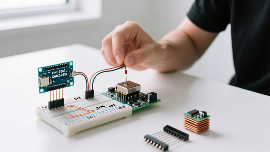
Standard Pinout for Arduino Uno R3 / Nano
- VCC: Connect to 5V (or 3.3V if using a 3.3V native board like the Arduino MKR series).
- GND: Connect to common ground.
- SCL: Connect to A5 (or dedicated SCL pin on newer Nano/Uno layouts).
- SDA: Connect to A4 (or dedicated SDA pin).
Expert Hardware Tip: If your I2C bus hangs or returns corrupted data, the module likely lacks adequate pull-up resistors. Solder external 4.7kΩ resistors between SDA/SCL and VCC. Furthermore, force the I2C clock speed down to 100kHz usingWire.setClock(100000);in yoursetup()function to ensure signal integrity over longer wire runs.
Step-by-Step Firmware Configuration
To configure your magnetometer Arduino integration, we will bypass bloated wrapper libraries initially and use the native Arduino Wire Library to verify communication. This ensures you understand exactly what is happening on the bus.
Step 1: The I2C Scanner Sanity Check
Never assume your sensor is wired correctly based on LED indicators. Upload the classic Arduino I2C Scanner sketch. If your module returns 0x0D, you have a QMC5883L. If it returns 0x1E, you have a genuine (and rare) HMC5883L. If it returns nothing, check your pull-up resistors and wiring.
Step 2: QMC5883L Register Initialization
Assuming you have the modern QMC5883L (0x0D), you must configure its internal control registers to output continuous data. The QMC5883L powers up in standby mode to save battery, which confuses many beginners who try to read data immediately.
You must write to Control Register 1 (0x09). To set the sensor to Continuous Mode, 50Hz Output Data Rate (ODR), 256x Oversampling Ratio (OSR), and a 2-Gauss full-scale range, you write the byte 0x11 to register 0x09.
Additionally, you must configure the Set/Reset Period Register (0x0B). The QST datasheet explicitly recommends writing 0x01 to this register for stable operation, a step omitted by many low-quality GitHub libraries.
Advanced Calibration: Defeating Magnetic Interference
Raw magnetometer data is virtually useless for precise navigation. The Earth's magnetic field is weak (roughly 0.25 to 0.65 Gauss), and the sensor will easily pick up 'hard iron' and 'soft iron' distortions from the Arduino's USB port, voltage regulators, and nearby steel chassis components.
Hard Iron vs. Soft Iron Distortion
- Hard Iron Interference: Caused by permanent magnets or magnetized components (like speakers or motors). This creates a constant additive offset to the X, Y, and Z axes, shifting the center of your magnetic sphere away from the origin (0,0,0).
- Soft Iron Interference: Caused by ferromagnetic materials (like steel screws or PCB traces) that bend the Earth's magnetic field lines. This stretches and skews the magnetic sphere into an ellipsoid.
Implementing the Calibration Math
To calibrate, rotate your Arduino assembly in a full 3D figure-8 pattern while logging the raw X, Y, and Z maximum and minimum values. For a quick hard-iron correction, calculate the offset for each axis:
Offset_X = (Max_X + Min_X) / 2
Subtract this offset from your raw readings in real-time. For professional-grade robotics, use PC-based tools like MotionCal to generate a 3x3 soft-iron matrix and a 1x3 hard-iron vector, applying them via matrix multiplication in your Arduino sketch before calculating the heading.
Calculating True North: Magnetic Declination
A magnetometer points to Magnetic North, not True North. The angular difference between the two is called Magnetic Declination, and it varies wildly depending on your global coordinates. In parts of the US Pacific Northwest, declination can be +15 degrees, while in parts of Europe, it may be negative.
To get an accurate GPS-aligned heading, you must query the NOAA Magnetic Declination Calculator for your specific latitude and longitude. Convert the resulting degrees to radians and add it to your calculated heading:
float headingDegrees = headingRadians * 180 / PI;
headingDegrees += DECLINATION_ANGLE;
if(headingDegrees < 0) headingDegrees += 360;
if(headingDegrees > 360) headingDegrees -= 360;
Troubleshooting Common I2C Faults
If your magnetometer Arduino setup is failing, run through this diagnostic checklist:
- Nan or Zero Readings: The I2C bus is timing out. The sensor is likely stuck in standby mode because the initialization sequence failed. Verify your library is sending the correct wake-up bytes to 0x09.
- Wildly Fluctuating Headings: You have uncalibrated soft-iron distortion, or the sensor is mounted too close to the Arduino's switching voltage regulator. Move the sensor at least 2 inches away from the main MCU board using a ribbon cable.
- Heading 'Jumps' at 180 Degrees: This is a classic
atan2(y, x)math error. Ensure you are passing the Y-axis as the first argument and X-axis as the second argument to theatan2()function in C++. Reversing them will invert your compass rose.
By understanding the silicon you actually possess, managing I2C bus physics, and applying rigorous mathematical calibration, your magnetometer integration will yield reliable, drift-free heading data suitable for advanced autonomous navigation.