
The Essentials of TDS Meter Arduino Integration
Integrating a Total Dissolved Solids (TDS) sensor with an Arduino or ESP32 is a foundational skill for makers building automated hydroponic systems, aquaponics monitors, or reverse osmosis (RO) water quality loggers. According to the United States Geological Survey (USGS), TDS represents the sum of all inorganic and organic substances dissolved in a liquid. However, hobbyist and prosumer TDS modules do not measure solids directly; they measure Electrical Conductivity (EC) and apply a conversion factor to estimate TDS in Parts Per Million (PPM).
This quick reference guide and FAQ addresses the most common hardware bottlenecks, analog-to-digital conversion (ADC) pitfalls, and calibration protocols for TDS meter Arduino projects in 2026. Whether you are using a basic comparator module or a high-precision AC-excited probe, the following data will help you achieve laboratory-grade reliability.
Quick Reference: Top TDS Sensors for Microcontrollers
Selecting the correct sensor dictates your wiring topology and code complexity. Below is a 2026 market snapshot of the most common TDS modules used in the maker community.
| Sensor Model | Output Type | Excitation Method | Approx. Price (2026) | Best Use Case |
|---|---|---|---|---|
| DFRobot Gravity SEN0244 | Analog (0-3.3V / 0-5V) | AC (Internal) | $28.00 - $32.00 | Precision hydroponics, continuous logging |
| Keyestudio KS0428 | Analog (0-5V) | AC (Internal) | $15.00 - $18.00 | Educational kits, basic aquaculture |
| Generic LM393 TDS Module | Digital (HIGH/LOW) | DC | $4.00 - $7.00 | Threshold alarms (not PPM measurement) |
| Atlas Scientific EZO-EC | UART / I2C | AC (Advanced) | $140.00 - $160.00 | Commercial agriculture, lab equipment |
Frequently Asked Questions (FAQ)
1. How do I wire a 5V analog TDS sensor to a 3.3V ESP32?
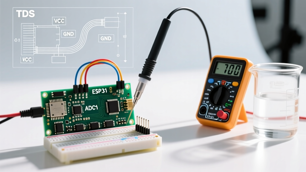
Most standard analog TDS modules are designed for 5V Arduino Uno boards and output a 0-5V analog signal. The ESP32, however, operates at 3.3V logic, and its SAR ADC pins will be damaged or yield saturated readings if subjected to 5V. Never connect a 5V analog out directly to an ESP32 GPIO.
Solution: Use a simple voltage divider to step the signal down. Connect a 10kΩ resistor in series with the sensor's analog out, and a 22kΩ resistor from the ESP32 GPIO to ground. This scales the 0-5V signal down to a safe 0-3.46V range. Alternatively, bypass the ESP32's internal ADC entirely and use an external I2C ADC like the Texas Instruments ADS1115, which provides 16-bit resolution and built-in programmable gain amplifiers (PGA).
2. Why are my analog TDS readings noisy and fluctuating wildly?
Fluctuating readings are the most common complaint in TDS meter Arduino forums. This is rarely a defect in the probe itself; it is almost always an ADC noise or grounding issue.
- Decoupling Capacitors: The Arduino Uno's ATmega328P ADC is highly susceptible to high-frequency noise from the board's switching regulators. Solder a 100nF (0.1µF) ceramic capacitor directly between the AREF pin and GND to stabilize the analog reference voltage.
- Oversampling in Software: Do not rely on a single
analogRead(). Take 16 to 32 rapid samples, discard the highest and lowest outliers, and average the remainder. This software low-pass filter dramatically stabilizes PPM readings. - Ground Loops: If your Arduino is powered via USB from a PC while simultaneously reading a TDS probe submerged in a grounded water tank, stray currents will corrupt the reading. Power the Arduino via an isolated battery or a high-quality isolated DC-DC buck converter.
3. How do I calibrate the sensor to standard PPM solutions?
Out of the box, analog TDS sensors rely on a generic linear equation that assumes a specific conversion factor (usually 0.5, which is accurate for NaCl but inaccurate for hydroponic nutrients). For precise measurements, you must perform a single-point or two-point calibration using standard buffer solutions.
- Acquire Calibration Fluid: Purchase a standard 342 ppm NaCl solution or a 1000 ppm KCl solution. (Note: Ensure your sensor's conversion factor matches the solution's chemical composition).
- Stabilize Temperature: Ensure the calibration fluid is exactly at 25°C (77°F). If it is not, you must apply temperature compensation before calibrating.
- Read Raw Voltage: Upload a bare-bones sketch that outputs the raw analog voltage (not the pre-calculated PPM). Submerge the probe, stir gently to remove air bubbles, and wait 3 minutes for thermal equilibrium.
- Calculate the Slope: If your 342 ppm solution reads 1.45V, your calibration slope is
342 / 1.45 = 235.86 ppm/V. Update your code's multiplication factor with this exact number.
4. Why is temperature compensation mandatory for accurate TDS?
Water conductivity increases by approximately 1.9% to 2.5% for every 1°C rise in temperature. A nutrient solution measuring 800 ppm at 20°C will read nearly 900 ppm at 30°C, even though the actual dissolved solids have not changed. According to the DFRobot SEN0244 technical documentation, failing to compensate for temperature renders TDS data useless for automated dosing systems.
Implementation: Wire a waterproof DS18B20 temperature probe alongside your TDS sensor. In your Arduino sketch, read the temperature first, then apply the standard compensation formula:
EC_25 = EC_measured / (1 + alpha * (Temp_C - 25.0))
Where alpha is the temperature coefficient (typically 0.019 for hydroponic nutrients). Calculate the compensated EC, then multiply by your TDS conversion factor.
5. What causes probe polarization and how do I prevent it?
Cheap, generic TDS modules often drive the probe with a direct current (DC). When DC voltage is applied to water, electrolysis occurs. Ions migrate to the electrodes, creating a gas bubble layer and an opposing polarization voltage. This causes the TDS reading to drift downward continuously over a few hours, eventually ruining the probe's metal contacts.
Expert Rule of Thumb: Never use DC-excited TDS probes for continuous monitoring. Always invest in modules that utilize AC excitation (alternating the polarity thousands of times per second). The DFRobot SEN0244 and Atlas Scientific modules use internal AC oscillators specifically to prevent electrolysis and probe degradation.
Advanced Troubleshooting & Edge Cases
When your hardware is wired correctly but the data still looks wrong, consult this edge-case matrix:
- ESP32 ADC Non-Linearity: The original ESP32 (WROOM-32) has a notoriously non-linear internal ADC, particularly below 0.15V and above 2.6V. If your TDS sensor outputs 4.2V for a highly concentrated solution, the ESP32 will compress the reading, resulting in massive under-reporting of PPM. Fix: Use an ESP32-S3 (which features an improved ADC) or an external ADS1115 module.
- Stray Capacitance on Long Wires: Running a 3-wire analog TDS sensor cable longer than 1 meter introduces parasitic capacitance, which acts as a low-pass filter and slows down the sensor's response time while inviting 50/60Hz mains hum. Fix: Keep analog traces under 50cm. If long distances are required, mount an I2C ADC (like the ADS1115) directly next to the probe and run digital I2C lines back to the MCU.
- Air Bubbles on the Probe: Micro-bubbles clinging to the sensing rings will insulate the electrodes from the water, causing sudden, erratic drops in PPM readings. Fix: Design your 3D-printed probe housing with a slight upward angle to allow bubbles to naturally escape, or implement a software routine that ignores sudden >20% drops in PPM that recover within 2 seconds.
For further reading on optimizing analog sensor inputs, refer to the official Arduino documentation on analog pins and ADC resolution. Mastering these hardware and software nuances will elevate your TDS meter Arduino project from a noisy science experiment to a robust, deployment-ready environmental monitor.