
The Physics of Direct Time-of-Flight (dToF) in Microcontrollers
Integrating spatial awareness into an Arduino project fundamentally changes how your microcontroller interacts with the physical world. While ultrasonic sensors and infrared proximity arrays have their place, LiDAR (Light Detection and Ranging) offers unparalleled precision, speed, and immunity to acoustic noise. To effectively build a LiDAR Arduino system, we must first understand the underlying physics of Direct Time-of-Flight (dToF).
Unlike phase-shift LiDAR used in high-end industrial surveying equipment, the compact LiDAR modules designed for microcontrollers rely on dToF. The sensor emits a highly collimated pulse of laser light—typically at a 905nm wavelength using a Vertical-Cavity Surface-Emitting Laser (VCSEL). This pulse travels to the target, scatters, and a fraction of the photons return to the sensor's avalanche photodiode (APD) or PIN receiver.
Because light travels at approximately 299,792 kilometers per second, measuring the distance to an object just one meter away requires timing the pulse round-trip with a resolution of roughly 6.6 picoseconds. The internal Time-to-Digital Converter (TDC) inside the LiDAR module handles this extreme temporal resolution, calculating the distance and outputting it via digital interfaces like UART or I2C. The Arduino simply reads the processed data, abstracting away the picosecond timing requirements.
Distinguishing True LiDAR from SPAD Proximity Sensors
A common point of confusion in the maker community is the conflation of true LiDAR modules with Single-Photon Avalanche Diode (SPAD) Time-of-Flight proximity sensors. While both use the speed of light to measure distance, their optical architectures and effective ranges differ drastically.
Sensors like the popular STMicroelectronics VL53L1X are frequently marketed as 'LiDAR' by hobbyist vendors. However, they are technically multi-zone SPAD ToF sensors. They rely on a broad flood of VCSEL light and an array of photon-counting diodes. They excel at short-range precision (up to 4 meters) and gesture recognition but suffer from severe beam divergence, making them unsuitable for long-range mapping or narrow-beam obstacle avoidance.
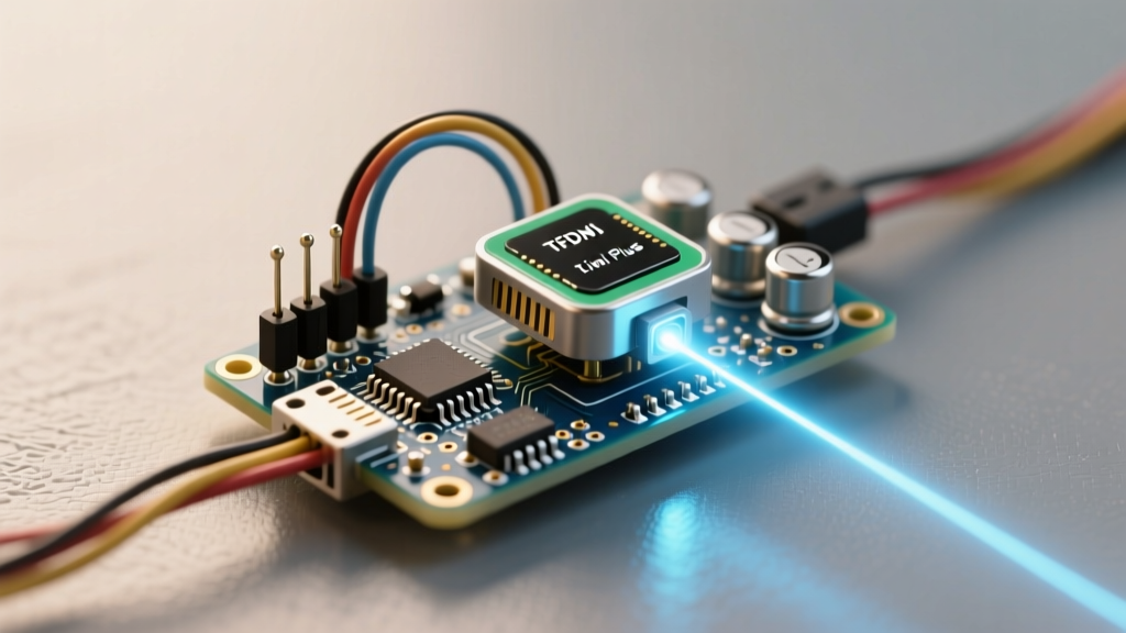
True microcontroller-scale LiDAR, such as the Benewake TFMini Plus or the Garmin LiDAR-Lite v3, utilizes focused optical lenses to maintain a tight beam divergence (often under 2 degrees). This allows them to accurately measure distances up to 12 meters or more, isolating specific physical features rather than averaging out a wide cone of infrared light.
Sensor Comparison Matrix: Architectures and Specifications
| Feature | ST VL53L1X (SPAD ToF) | Benewake TFMini Plus (True LiDAR) | Garmin LiDAR-Lite v3 (True LiDAR) |
|---|---|---|---|
| Technology | Multi-zone SPAD dToF | Collimated VCSEL dToF | Collimated Laser dToF |
| Max Range | ~4.0 Meters | ~12.0 Meters | ~40.0 Meters |
| Beam Divergence | ~27 Degrees (Wide) | ~2.3 Degrees (Narrow) | ~2.0 Degrees (Narrow) |
| Primary Interface | I2C | UART / I2C | I2C / PWM |
| Avg. Price (USD) | $12.00 - $18.00 | $35.00 - $45.00 | $140.00 - $160.00 |
For robotic navigation and precise distance mapping, the narrow beam divergence of the TFMini Plus makes it the superior choice for most intermediate Arduino projects. You can explore the official datasheets and integration examples on the Benewake TFMini Plus GitHub repository.
Hardware Integration: The Power Delivery Bottleneck
The most frequent cause of failure in LiDAR Arduino projects is inadequate power delivery. Firing a 905nm VCSEL laser requires sudden, massive bursts of current. While the average current draw of a module like the TFMini Plus might be listed as 140mA, the peak transient current during the actual laser pulse can spike significantly higher.
Many hobbyists attempt to power these sensors directly from the Arduino Nano or Uno's onboard 3.3V or 5V voltage regulators. The cheap linear regulators (like the AMS1117 clones found on budget microcontroller boards) cannot respond fast enough to these transient spikes. This results in voltage sag, which causes the internal microcontroller of the LiDAR sensor to brownout and reset mid-transmission. The symptom is a stream of corrupted, garbage data on the Arduino's serial monitor.
The Capacitor and Regulator Solution
To stabilize the power rail, you must implement a dedicated power delivery circuit:
- Low-ESR Decoupling: Solder a 470µF low-ESR electrolytic capacitor and a 0.1µF ceramic capacitor directly across the VCC and GND pins of the LiDAR sensor. This acts as a local energy reservoir to satisfy the VCSEL's transient demands.
- Dedicated LDO or Buck Converter: Bypass the Arduino's onboard regulator entirely. Use a dedicated 3.3V LDO (like the AP2112K-3.3) or a 5V buck converter capable of supplying at least 500mA continuous current, powered directly from your main battery pack.
Logic Level Translation: Preventing Silicon Death
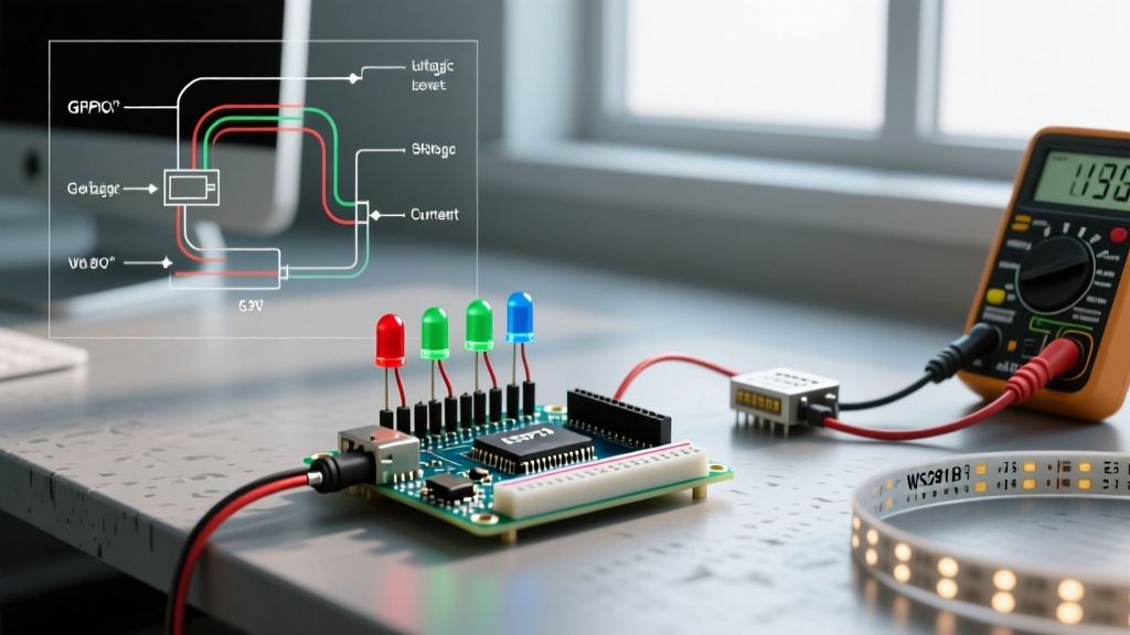
Another critical hardware concept is logic level compatibility. Most modern, high-performance LiDAR modules operate at 3.3V logic levels. If you are using a 5V Arduino (like the Uno, Mega, or standard Nano), the TX pin on the Arduino outputs 5V. Connecting a 5V TX line directly to the 3.3V RX pin of a LiDAR module will likely destroy the sensor's internal UART receiver over time due to overvoltage stress.
Always use a bidirectional logic level converter (such as a BSS138 MOSFET-based module) or a simple resistor voltage divider (e.g., a 2kΩ and 3.3kΩ resistor network) to step down the Arduino's 5V TX signal to a safe 3.3V for the LiDAR's RX pin. The LiDAR's 3.3V TX signal is generally recognized as a logical 'HIGH' by the Arduino's 5V RX pin, so the return line usually does not require stepping up.
Software Architecture: Parsing UART State Machines
Unlike I2C sensors where you simply request a register, UART-based LiDAR sensors continuously stream data frames. The TFMini Plus, for example, outputs a 9-byte frame at 115200 baud. The frame structure begins with a two-byte header (0x59 0x59), followed by distance data, signal strength, temperature, and a checksum.
Using blocking code like Serial.readBytes() is a dangerous practice in embedded systems, as it halts the Arduino's main loop, preventing motor control or safety checks from executing. Instead, professional firmware relies on a non-blocking UART State Machine.
Implementing the State Machine
A robust parsing algorithm cycles through distinct states every time the serialEvent() or a non-blocking serial check runs:
- State 0 (Header Sync): Discard incoming bytes until the first
0x59is detected. Transition to State 1. - State 1 (Header Verification): Check if the next byte is also
0x59. If yes, transition to State 2. If no, revert to State 0. - State 2 (Payload Accumulation): Read the next 6 bytes into a buffer array.
- State 3 (Checksum Validation): Sum the first 8 bytes (header + payload) and perform a modulo 256 operation. Compare the result to the 9th byte (the checksum). If they match, the distance data is valid and can be committed to a global variable. If they fail, discard the frame and return to State 0.
This state-machine approach ensures that even if electrical noise corrupts a single byte in the stream, the Arduino will gracefully drop the bad frame and re-sync on the next valid header without crashing the main loop.
Expert Insight: When debugging UART LiDAR streams, avoid relying solely on the Arduino IDE Serial Monitor. Use a dedicated hardware logic analyzer (like a Saleae clone) or an FTDI USB-to-Serial adapter connected to a PC running a terminal program. This allows you to verify if the sensor is actually outputting data, isolating whether the failure is optical, electrical, or purely in your Arduino parsing logic.
Environmental Failure Modes and Optical Physics
Understanding how light interacts with materials is crucial for deploying a LiDAR Arduino system in the real world. dToF sensors are not infallible; they are bound by the laws of optics.
- Specular Reflection (Mirrors and Glass): If the laser hits a mirror or a pane of glass at an oblique angle, the beam will reflect away from the sensor's receiver lens. The sensor will either report a maximum distance error or read the object behind the glass. For robotic navigation, always pair LiDAR with ultrasonic sensors to detect transparent barriers.
- Albedo and Light Absorption: Dark, matte materials (like black rubber tires or Vantablack-style coatings) absorb 905nm infrared light rather than scattering it back. The TFMini Plus will report a 'low signal strength' flag in its data frame when targeting low-albedo surfaces. Always monitor the signal strength byte, not just the distance byte, to determine if a reading is trustworthy.
- Ambient Light Saturation: While 905nm VCSELs are paired with narrow-bandpass optical filters to block visible light, direct sunlight contains massive amounts of infrared radiation. Pointing a microcontroller LiDAR sensor directly into the sun will saturate the APD receiver, effectively blinding it. Mount your sensors with physical 3D-printed hoods or shrouds to limit the field of view to the necessary detection cone.
For deeper hardware specifications regarding alternative modules, review the Garmin LiDAR-Lite v3 documentation on SparkFun, or consult the STMicroelectronics VL53L1X product page for SPAD-based alternatives. By mastering the physics, power delivery, and software parsing concepts outlined above, you can elevate your Arduino projects from simple obstacle-avoiders to sophisticated, spatially-aware machines.