
The Hidden Cost of Hardware-Only Prototyping
For embedded systems engineers and DIY makers, the physical breadboard is both a canvas and a bottleneck. While physically wiring an ATmega328P or an Arduino Nano clone is essential for final validation, relying exclusively on hardware for initial code iteration is a fundamentally flawed workflow. As of 2026, the cost of a generic Nano clone hovers around $3.50, and a bare ATmega328P-PU chip costs about $2.50. However, the true cost of hardware-only prototyping isn't measured in burnt silicon—it's measured in time. Troubleshooting a faulty I2C bus due to a loose jumper wire, or debugging a logic error that accidentally sets an I/O pin HIGH against a grounded component, drains hours of productive development time.
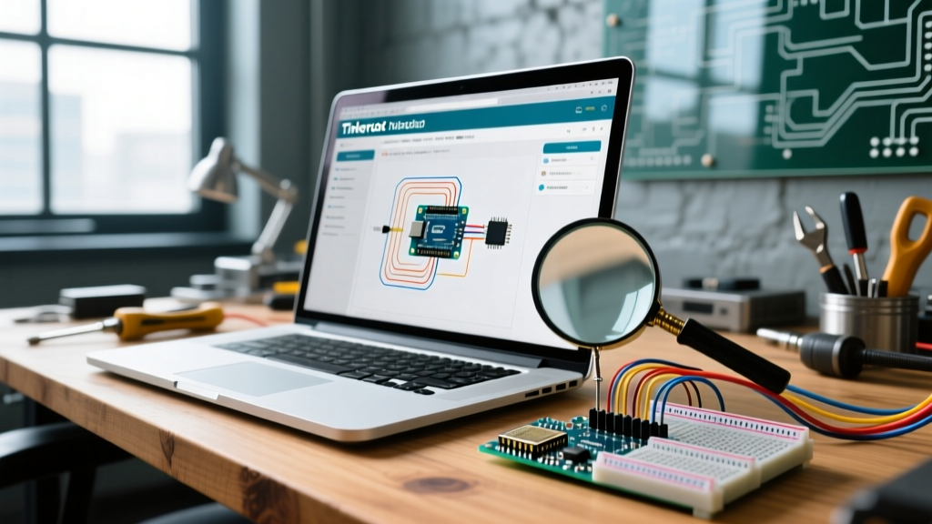
This is where the tinkercad arduino simulator transitions from a simple educational toy to a mission-critical workflow optimization tool. By front-loading your circuit validation and code compilation in a cloud-based virtual environment, you can eliminate 80% of wiring and logic errors before a single physical component is touched.
Architecting a High-Velocity Virtual Workspace
To use the simulator professionally, you must move beyond basic LED blinking and treat the virtual workspace as a digital twin of your physical bench. According to the Autodesk Tinkercad Learning Portal, the platform supports a vast library of discrete components, ICs, and sensors, but workflow speed depends on how you manage them.
1. Component Grouping and Sub-Circuit Isolation
When designing complex systems—such as a weather station utilizing a BME280 sensor, an SD card module, and a 16x2 I2C LCD—the virtual breadboard quickly becomes a rat's nest of colored wires. Optimize your workflow by using the 'Group' function. Build your sensor interface on one side of the breadboard and your actuator/display interface on the other. This mirrors professional PCB layout strategies, separating low-voltage logic from higher-current driver circuits.
2. Leveraging the Virtual Serial Monitor for Data Parsing
The serial monitor in the simulator is your primary debugging instrument. Instead of using basic Serial.println() statements, format your virtual serial output as CSV or JSON. This allows you to copy the serial output directly from the simulator and paste it into a Python script or Excel sheet to graph sensor drift or validate PID tuning loops before deploying to physical hardware.
Advanced Simulation: I2C, SPI, and Interrupts
The true test of any MCU simulator is its handling of serial communication protocols and hardware interrupts. The Official Arduino Language Reference outlines strict timing requirements for protocols like I2C, which the simulator approximates but does not perfectly replicate.
Simulating I2C Pull-Up Dynamics
In the physical world, an I2C bus requires 4.7kΩ pull-up resistors on the SDA and SCL lines to function reliably, especially at 400kHz Fast Mode. The simulator's virtual Arduino often includes internal pull-up emulation that masks missing external resistors. Workflow Rule: Always manually place 4.7kΩ resistors to VCC in your virtual circuit. If your code works in the simulator without them, it will likely fail on a physical breadboard due to capacitance and signal degradation. Training yourself to include them virtually builds rigorous hardware habits.
The Interrupt Latency Edge Case
Hardware interrupts via attachInterrupt() are supported in the simulator, making it excellent for testing rotary encoders or basic button debouncing. However, the simulator runs on a JavaScript execution thread in your browser. It cannot guarantee the microsecond-level precision required for bit-banging protocols like WS2812B (NeoPixel) LEDs or decoding 38kHz IR remote signals. If your workflow involves high-frequency timing, use the simulator for state-machine logic, but defer signal-decoding validation to physical hardware.
Workflow Metrics: Virtual vs. Physical Iteration
Integrating the simulator into your development pipeline yields measurable improvements in iteration speed and resource conservation. Below is a comparative analysis of a standard 10-iteration debugging cycle for a motor-control circuit.
| Metric | Hardware-Only Workflow | Simulator-First Workflow |
|---|---|---|
| Average Iteration Time | 14 minutes (rewiring, uploading) | 3 minutes (code tweak, instant run) |
| Component Burnout Risk | High (approx. 1-2 blown ICs per project) | Zero (virtual components are indestructible) |
| Code Compilation Wait | 45-60 seconds per upload via USB | Instantaneous cloud compilation |
| Oscilloscope Access | Requires $250+ physical hardware | Free virtual oscilloscope included |
Bridging the Gap: Transitioning to Physical Hardware
The most critical phase of workflow optimization is the handoff from the virtual environment to the physical workbench. A common failure mode occurs when makers blindly trust the simulator's pinout assignments without verifying physical board constraints.
Pro-Tip: The simulator defaults to the Arduino Uno R3 footprint. If your final physical build uses an Arduino Nano or a bare ATmega328P on a perfboard, remember that pins A6 and A7 exist on the Nano's ATmega328P-AU chip but are strictly analog inputs and cannot be used as digital I/O, unlike the virtual environment which sometimes allows flexible pin mapping.
Exporting the Bill of Materials (BOM)
Before closing your browser tab, utilize the simulator's export features. While it doesn't natively export to KiCad or Altium, you can generate a clean BOM and a high-resolution schematic screenshot. Paste this into your project documentation or GitHub repository. This creates a permanent record of the validated virtual state, which is invaluable when you inevitably need to troubleshoot the physical build three months later.
Managing Simulation Time Drift
Be aware that complex circuits in the simulator experience 'time drift.' A delay(1000) might take 1.2 seconds in the simulation engine due to browser overhead. If your code relies on precise millis() timing for baud-rate generation or software serial, expect a 5-10% timing variance between the simulator and the physical 16MHz crystal oscillator. Always use hardware serial (Serial) instead of SoftwareSerial when prototyping in the cloud to avoid dropped bytes.
Frequently Asked Questions (FAQ)
Can I import custom third-party libraries into the simulator?
No. The simulator operates in a sandboxed environment and only supports a curated list of standard and highly popular libraries (e.g., Wire.h, Servo.h, LiquidCrystal.h). If your workflow relies on niche GitHub libraries, you must write a 'mock' version of the library's core functions using standard C++ to test your logic in the simulator before deploying the real library to hardware.
Does the virtual oscilloscope accurately represent PWM signals?
Yes, but with caveats. The virtual oscilloscope accurately displays the 490Hz and 980Hz PWM frequencies native to the ATmega328P. However, if you are manipulating Timer1 registers directly to generate custom 20kHz PWM for motor drivers, the simulator's math engine may struggle to render the waveform accurately. Use the simulator to verify register logic, but verify the analog output with a physical oscilloscope.
How do I simulate analog sensor noise?
The simulator provides perfectly clean, noiseless analog signals from virtual potentiometers and sensors. To optimize your workflow and test your software filtering (like moving average or Kalman filters), inject mathematical noise directly into your code using the random() function added to your virtual analogRead() values. This forces your code to handle real-world signal degradation before you ever wire up a physical sensor.