
The Ultimate LCD1602A Arduino Quick-Reference Guide
Despite the proliferation of OLEDs and TFT screens, the LCD1602A Arduino setup remains a foundational pillar in electronics prototyping. Based on the ubiquitous Hitachi HD44780U controller, this 16x2 character display offers unmatched sunlight readability, minimal resource overhead, and extreme cost-effectiveness (typically $3.00 to $5.50 per unit in 2026). Whether you are wiring it in standard 4-bit parallel mode or using a PCF8574 I2C backpack, this FAQ and quick-reference guide addresses the most common hardware, software, and troubleshooting hurdles makers face.
Quick-Reference Pinout Matrix
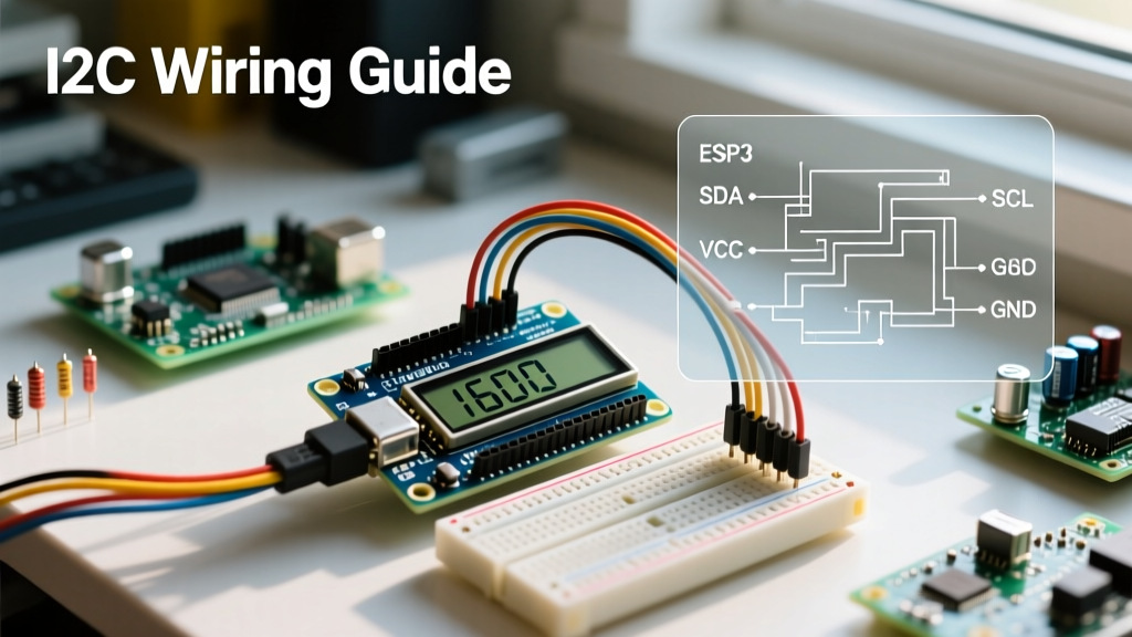
Before diving into troubleshooting, verify your physical connections against this matrix. The LCD1602A can be driven via a 16-pin parallel interface or a 4-pin I2C backpack.
| Pin / Function | Parallel (16-Pin) | I2C Backpack (4-Pin) | Notes & Specifications |
|---|---|---|---|
| VSS (Ground) | Pin 1 | GND | Common ground with MCU |
| VDD (Power) | Pin 2 | VCC | 5V DC (4.5V to 5.5V tolerance) |
| V0 (Contrast) | Pin 3 | Managed by Backpack | Requires ~0.4V - 0.8V for optimal contrast |
| RS (Register Select) | Pin 4 | Managed by Backpack | HIGH = Data, LOW = Command |
| RW (Read/Write) | Pin 5 | Managed by Backpack | Must be tied to GND for write-only mode |
| E (Enable) | Pin 6 | Managed by Backpack | Falling edge triggers data latch |
| D4-D7 (Data Lines) | Pins 11-14 | Managed by Backpack | Used for 4-bit mode communication |
| A (Backlight Anode) | Pin 15 | Managed by Backpack | Requires current limiting if no onboard resistor |
| K (Backlight Cathode) | Pin 16 | Managed by Backpack | Connect to GND |
| SDA / SCL | N/A | SDA / SCL | I2C Data and Clock lines |
Hardware & Wiring FAQs
Q: Do I need a current-limiting resistor for the backlight (Pins 15 & 16)?
A: It depends on your specific module revision. Many modern LCD1602A boards include a built-in 10Ω or 100Ω surface-mount resistor on the back (often labeled R8 or near a J1 jumper). If your board has this resistor, you can connect Pin 15 directly to 5V. If it does not, you must add an external 100Ω to 220Ω resistor in series with Pin 15 to limit the current to ~20mA. Applying 5V directly to an unprotected backlight LED will result in immediate thermal failure.
Q: How do I set the contrast (V0 / Pin 3) without a bulky potentiometer?
A: While a 10kΩ trimpot is the standard method, you can use a fixed resistor for a cleaner breadboard layout. The HD44780U controller requires the V0 pin to be approximately 0.4V to 0.8V lower than VDD for optimal contrast. By connecting a 1kΩ resistor between Pin 3 (V0) and GND, you create a voltage divider that yields roughly 0.5V, which is perfect for most 5V LCD1602A modules operating at room temperature.
Q: Why does my parallel LCD show garbage characters after a few minutes?
A: This is almost always a power integrity or grounding issue. The LCD1602A draws transient current spikes when the backlight switches or when the charge pump drives the LCD matrix. If your breadboard ground rails have high impedance, the logic levels shift, causing the HD44780 to lose its 4-bit synchronization state. Fix: Solder or place a 0.1µF ceramic decoupling capacitor directly across Pins 1 (GND) and 2 (VDD) on the back of the LCD PCB. For authoritative wiring practices, refer to the Adafruit Character LCD Guide.
I2C Backpack & Addressing FAQs
Q: Why won't my I2C LCD1602A respond to the default 0x27 address?
A: I2C backpacks use an I/O expander chip, typically the NXP PCF8574. However, there are two common variants:
- PCF8574T: Default I2C address is
0x27. - PCF8574AT: Default I2C address is
0x3F.
Furthermore, the backpack features three jumper pads (A0, A1, A2). If these are bridged with solder, the address shifts according to the NXP PCF8574 Datasheet. Always run an I2C scanner sketch before assuming your hardware is defective.
Q: What is the I2C Scanner code for Arduino?
A: Upload this minimal sketch to your Arduino to poll the I2C bus and print the exact hexadecimal address of your LCD backpack to the Serial Monitor (set to 9600 baud).
#include <Wire.h>

void setup() {
  Wire.begin();
  Serial.begin(9600);
  while (!Serial); // Wait for serial monitor (Leo/Micro)
  Serial.println("I2C Scanner");
}

void loop() {
  byte error, address;
  int nDevices = 0;
  for(address = 1; address < 127; address++ ) {
    Wire.beginTransmission(address);
    error = Wire.endTransmission();
    if (error == 0) {
      Serial.print("I2C device found at address 0x");
      if (address < 16) Serial.print("0");
      Serial.print(address, HEX);
      Serial.println("  !");
      nDevices++;
    }
  }
  if (nDevices == 0) Serial.println("No I2C devices found\n");
  delay(5000);
}
Q: What is the maximum reliable cable length for I2C to the LCD?
A: The I2C specification limits bus capacitance to 400pF. Using standard jumper wires, this translates to roughly 30 centimeters (12 inches) at the standard 100kHz clock speed. If you need to mount the LCD1602A further away (e.g., in an enclosure door), you must add 4.7kΩ pull-up resistors to both SDA and SCL lines at the Arduino end, and ideally drop the I2C clock speed to 50kHz in your software initialization.
Software & Library FAQs
Q: Which library is best for the LCD1602A Arduino setup in 2026?
A: The legacy LiquidCrystal_I2C library by Frank de Brabander is still widely used, but it requires hardcoding pin mappings that vary wildly between backpack manufacturers. As of 2026, the industry-standard recommendation for advanced makers is the hd44780 library by Bill Perry (available via the Arduino Library Manager). It features an auto-diagnostics mode, automatically detects the I2C address, and maps the PCF8574 pins to the HD44780 internally, eliminating the "white block" initialization errors common with older libraries. You can review standard parallel implementations via the Official Arduino LiquidCrystal Documentation.
Q: Why does my code compile, but the LCD only shows a solid white backlight?
A: This indicates the backlight is receiving power, but the HD44780 controller is not receiving data or is stuck in an uninitialized state. In 4-bit parallel mode, the Arduino must send a specific "wake-up" sequence (three 0x03 commands followed by a 0x02 command) to force the LCD out of its default 8-bit hardware reset state. If your wiring is off by even one pin (e.g., swapping D4 and D5), this handshake fails silently, leaving the screen blank. Double-check your D4-D7 pin assignments in the LiquidCrystal(rs, en, d4, d5, d6, d7) constructor.
Rapid Troubleshooting Matrix
Use this diagnostic table to quickly resolve the most common LCD1602A anomalies.
| Symptom | Probable Root Cause | Actionable Fix |
|---|---|---|
| Top row displays solid black boxes | Contrast voltage (V0) is too high. | Adjust trimpot to lower V0 to ~0.5V, or swap fixed resistor to 1kΩ. |
| Screen completely blank (no backlight) | Power delivery failure or blown backlight. | Check VDD/GND with multimeter. Verify 5V at Pin 2. Check for missing backlight resistor. |
| Text prints backwards or mirrored | Incorrect entry mode command sent. | Ensure lcd.leftToRight() is called in setup(). Check for corrupted library cache. |
| Display works, but freezes randomly | EMI interference or floating RW pin. | Tie RW (Pin 5) directly to GND. Route I2C/Parallel cables away from AC motors/relays. |
| Only half the characters appear | Operating in 8-bit mode with 4 wires. | Verify library is initialized for 4-bit mode. Check D4-D7 continuity. |
Pro-Tip for Enclosure Builders: When mounting an LCD1602A behind a laser-cut acrylic or 3D-printed bezel, the viewing angle can shift dramatically. The HD44780U is optimized for a 6 o'clock viewing angle. If your text appears inverted or washed out in the final enclosure, gently adjust the contrast trimpot while viewing from the intended user position, not straight-on from the workbench.