
Why Bang-Bang Control Fails: The Case for PID
If you have been searching for a robust pid con arduino implementation, you likely already know that simple bang-bang (on/off) control is insufficient for precision thermal management. In a bang-bang system, the heater turns on when the temperature drops below the setpoint and turns off when it exceeds it. This guarantees continuous oscillation, thermal stress on your heating elements, and unacceptable overshoot in sensitive applications like reflow ovens, sous-vide baths, or 3D printer hotends.
A Proportional-Integral-Derivative (PID) controller solves this by calculating an error value and applying a correction based on proportional, integral, and derivative terms. In this 2026 updated guide, we will build a high-precision, solid-state relay (SSR) driven temperature controller using the Arduino Uno R4 Minima, moving past outdated components and addressing the critical hardware traps that cause most maker projects to fail.
Hardware BOM: 2026 Precision Standard
To achieve professional-grade stability, we must abandon the outdated MAX6675 thermocouple amplifier (which lacks proper cold-junction linearization) and standard mechanical relays. Below is the optimized Bill of Materials for a 120V/240V AC heating system.
| Component | Recommended Model | Approx. Cost (2026) | Engineering Purpose |
|---|---|---|---|
| Microcontroller | Arduino Uno R4 Minima | $20.00 | 14-bit DAC, 48MHz Cortex-M4 for fast PID compute loops. |
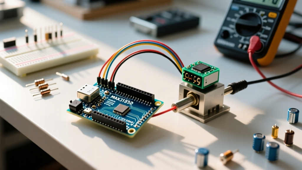
| Sensor Amplifier | Adafruit MAX31856 Breakout | $19.95 | 19-bit resolution, linearization for K-Type thermocouples. |
| Thermocouple | K-Type Fiberglass Insulated | $12.50 | Fast thermal response time, rated up to 480°C. |
| Switching Element | Omron G3NA-210B (SSR) | $28.00 | Zero-crossing AC SSR, 10A @ 240VAC, built-in snubber. |
| Heater (Test) | 150W Silicone Band Heater | $22.00 | Low thermal mass for rapid tuning and testing. |
The SSR Switching Trap: Why Standard PWM Destroys Hardware
The most common point of failure in DIY thermal projects is the misuse of Pulse Width Modulation (PWM) with AC Solid State Relays. The Arduino's analogWrite() function outputs a PWM signal at approximately 490Hz. However, AC SSRs like the Omron G3NA utilize internal zero-crossing detection circuits to switch the AC load safely and minimize Electromagnetic Interference (EMI).
Critical Engineering Warning: If you feed a 490Hz PWM signal into an AC zero-crossing SSR, the relay will attempt to switch hundreds of times per second. Because the SSR can only actually switch when the AC sine wave crosses zero volts, the internal triac will misfire, latch up, or overheat catastrophically. You must use Time Proportional Control (Slow PWM) with a window size between 1000ms and 5000ms.
Implementing Time Proportional Output
Instead of rapidly toggling the pin, we define a 'Window Size' (e.g., 2000ms). The PID algorithm outputs a value between 0 and 2000. If the PID output is 1500, the Arduino holds the SSR trigger pin HIGH for 1500ms, and LOW for the remaining 500ms of the window. This respects the AC zero-crossing circuitry while providing granular power control.
Step-by-Step Wiring & Isolation
Proper isolation is mandatory when mixing 5V DC logic with 120V/240V AC mains.
- Thermocouple Wiring: Connect the K-Type probe to the MAX31856 breakout. Ensure the thermocouple wires do not run parallel to the AC heater wires to prevent inductive noise coupling, which manifests as erratic derivative spikes in the PID calculation.
- SPI Bus: Wire the MAX31856 to the Uno R4 using the hardware SPI pins (SCK: 13, MISO: 12, MOSI: 11, CS: 10). Hardware SPI is mandatory to prevent blocking the main loop during temperature reads.
- SSR Trigger: Connect Arduino Digital Pin 3 to the SSR input (+). Connect Arduino GND to the SSR input (-). The Omron G3NA requires only 5mA to trigger, well within the Uno R4's 20mA per-pin limit. No external transistor is needed.
- AC Mains: Wire the Live (L) AC line through the SSR's output terminals (3 and 4) in series with your heating element. The Neutral (N) line connects directly to the heater. Always use a physical mechanical switch or breaker in series with the SSR for emergency disconnects.
Coding the PID con Arduino Controller
We will utilize the industry-standard Arduino PID Library by Brett Beauregard. It handles the complex calculus, derivative filtering, and integral windup prevention automatically.
Core Setup and Compute Loop
Below is the structural logic for the Time Proportional Output loop. This ensures your PID compute rate matches your sensor read rate.
#include <PID_v1.h>

#define PIN_INPUT 0 // Analog or SPI read mapped to double
#define PIN_OUTPUT 3 // SSR Trigger Pin

//Define Variables we'll be connecting to
double Setpoint, Input, Output;

//Specify the links and initial tuning parameters
double Kp=50, Ki=0.8, Kd=200;
PID myPID(&Input, &Output, &Setpoint, Kp, Ki, Kd, DIRECT);

int WindowSize = 2000; // 2 Second Slow PWM Window
unsigned long windowStartTime;

void setup() {
  windowStartTime = millis();
  Setpoint = 150.0; // Target 150C
  myPID.SetOutputLimits(0, WindowSize);
  myPID.SetSampleTime(250); // Compute every 250ms
  myPID.SetMode(AUTOMATIC);
  pinMode(PIN_OUTPUT, OUTPUT);
}

void loop() {
  Input = readMAX31856Temp(); // Your SPI read function
  myPID.Compute();

  // Time Proportional Output Logic
  unsigned long now = millis();
  if(now - windowStartTime > WindowSize) {
    windowStartTime += WindowSize;
  }
  if(Output > now - windowStartTime) {
    digitalWrite(PIN_OUTPUT, HIGH);
  } else {
    digitalWrite(PIN_OUTPUT, LOW);
  }
}
Auto-Tuning via Ziegler-Nichols
Guessing Kp, Ki, and Kd values is a waste of time. For a new thermal system, you should employ the Ziegler-Nichols tuning method. While you can do this manually by setting Ki and Kd to zero and increasing Kp until the system oscillates continuously (finding the Ultimate Gain, Ku), the modern maker approach uses the companion PID AutoTune Library.
The AutoTune library injects a relay-feedback test, forcing the heater on and off to measure the system's thermal lag and natural oscillation period. It then mathematically calculates the optimal Kp, Ki, and Kd values for your specific heater mass and insulation profile. Run the AutoTune sketch once, record the serial monitor output, and hardcode those values into your production firmware.
Troubleshooting Real-World Edge Cases
Even with perfect code, physical thermal systems present unique edge cases. Refer to the official Arduino hardware documentation for microcontroller-specific timing quirks, but focus on these PID-specific failure modes:
- Derivative Kick: When you change the Setpoint suddenly, the derivative term sees a massive instantaneous error change, causing the PID output to spike to 100%. The Beauregard library solves this by calculating the derivative based on the change in Input (measurement) rather than the change in Error. Ensure you are using 'Derivative on Measurement' mode if sudden setpoint shifts are required.
- Integral Windup: If your heater is undersized and cannot reach the setpoint, the Integral term will accumulate endlessly (wind up). When the system finally cools down or the setpoint is lowered, the massive accumulated integral value will cause severe overshoot. The library's
SetOutputLimits()function inherently clamps the total output, but you must ensure the limits match your physical Window Size exactly. - Sensor Noise Amplification: The Derivative term acts as a high-pass filter, meaning it amplifies high-frequency electrical noise. If your MAX31856 is picking up EMI from the AC SSR switching, the derivative term will cause erratic output jitter. Keep SPI lines short, use shielded thermocouple wire, and ensure the SSR is mounted away from the low-voltage logic.
Final Calibration and Safety Checks
Before leaving your pid con arduino system unattended, perform a 24-hour burn-in test. Monitor the SSR temperature; if the Omron G3NA requires a heatsink for your specific continuous load, the datasheet specifies thermal resistance curves. At 10A, a heatsink is mandatory. Precision thermal control is a marriage of robust code and uncompromising hardware safety. Respect the physics of your thermal mass, trust the math of the PID algorithm, and your system will hold temperature within ±0.5°C indefinitely.