
The Ultimate LCD 16x2 Arduino Quick Reference
The 16x2 character LCD, driven by the ubiquitous Hitachi HD44780 controller (or modern equivalents like the SPLC780D), remains a staple in maker projects. Despite its age, integrating an lcd16x2 arduino setup can still trip up both beginners and seasoned engineers, particularly when dealing with I2C backpack variations and logic-level mismatches. This FAQ and quick reference guide cuts through the noise, providing exact pinouts, modern library recommendations, and deep-dive troubleshooting for 2026.
Parallel vs. I2C Wiring Matrix
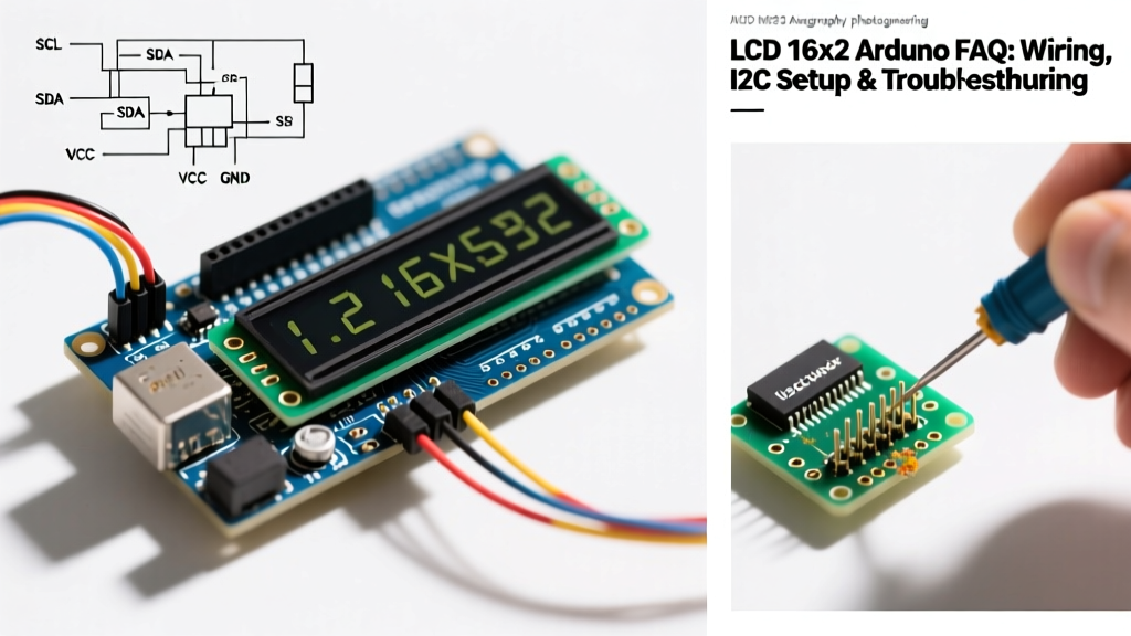
Before writing a single line of code, you must define your physical interface. While the raw parallel interface requires 6 digital pins, the I2C backpack reduces this to just 2 analog pins (SDA/SCL). Here is the definitive wiring matrix:
| Interface | Pins Required | Arduino Uno/Nano Pins | ESP32 Pins | Recommended Library |
|---|---|---|---|---|
| 4-Bit Parallel | 6 (RS, EN, D4, D5, D6, D7) | D12, D11, D5, D4, D3, D2 | Any GPIO | LiquidCrystal (Built-in) |
| I2C (PCF8574) | 2 (SDA, SCL) + VCC/GND | A4 (SDA), A5 (SCL) | GPIO 21 (SDA), GPIO 22 (SCL) | hd44780 (Bill Perry) |
Expert Note: Always tie the RW (Read/Write) pin to GND on parallel setups. The Arduino ecosystem almost exclusively uses write-only operations. Leaving RW floating or tying it to 5V will result in a blank screen or erratic garbage characters.
Hardware & Wiring FAQs
How do I find the correct I2C address for my backpack?
The most common point of failure in an lcd16x2 arduino project is an incorrect I2C address. Manufacturers use two primary I/O expanders for the backpack:
- PCF8574 (NXP/Texas Instruments): Default address is usually
0x27. - PCF8574A: Default address is usually
0x3F.
If your display isn't responding, do not guess. Upload an I2C Scanner sketch (available via the Arduino IDE Examples menu under Wire > I2CScanner). Open the Serial Monitor at 115200 baud, and the scanner will output the exact hex address of your display.
Why is the contrast pin (V0) critical, and how do I set it?
Pin 3 (V0) controls the liquid crystal bias voltage. If it is too high, you will see a solid row of black boxes. If it is too low, the screen will appear blank even if the backlight is on.
- The Standard Fix: Use a 10KΩ trimpot. Connect the outer legs to 5V and GND, and the wiper (middle leg) to V0.
- The Quick Hack: Modern high-efficiency LCDs often display perfectly with V0 tied directly to GND, or via a 1KΩ resistor to GND. This eliminates the need for a physical potentiometer in permanent installations.
Software & Library FAQs
Which library should I use in 2026?
For years, the community relied on the Arduino LiquidCrystal library for parallel, and various forked LiquidCrystal_I2C libraries for backpacks. However, the legacy I2C libraries are notoriously fragile because they hardcode pin mappings that vary wildly between cheap clone manufacturers.
The Modern Standard: Use the hd44780 library by Bill Perry. Available in the Library Manager, its hd44780_I2Cexp class automatically diagnoses the I2C address, identifies the exact pin mapping of your specific backpack, and configures the display at runtime. It eliminates 90% of software-related blank screen issues.
How do I generate and print custom characters?
The HD44780 controller features 64 bytes of Character Generator RAM (CGRAM), allowing you to define up to eight custom 5x8 pixel characters. Here is the exact workflow:
- Define a byte array of 8 elements, where each element represents a row (using binary
B00000toB11111). - Call
lcd.createChar(0, myCustomChar);duringsetup(). The first argument (0-7) is the memory slot. - Print it using
lcd.write((byte)0);orlcd.write(0);.
Use an online "LCD Character Generator" tool to visually draw your glyphs and export the C++ byte arrays.
Troubleshooting Common LCD 16x2 Arduino Failures
When your display refuses to cooperate, use this diagnostic matrix to isolate the fault.
| Symptom | Root Cause | Exact Fix |
|---|---|---|
| Solid row of black boxes on top line | Contrast voltage (V0) is too high; display is uninitialized. | Adjust 10K pot. If using I2C, check solder joints on the 16-pin header connecting the backpack to the LCD glass. |
| Backlight ON, screen completely blank | V0 too low, or SDA/SCL lines swapped. | Swap SDA/SCL. For ESP32, ensure you are using the correct GPIO pins (21/22) and not the Uno defaults (A4/A5). |
| Garbage characters / shifting text | RW pin floating; electrical noise on data lines. | Tie RW to GND. Add a 0.1µF decoupling capacitor across the LCD VCC and GND pins. |
| Display works, but text is mirrored/backwards | Incorrect pin mapping in legacy I2C library. | Switch to the hd44780_I2Cexp class to auto-detect the correct nibble mapping. |
| Intermittent freezing with multiple I2C devices | Missing I2C pull-up resistors on the bus. | Add 4.7kΩ pull-up resistors from SDA and SCL to the 5V rail. |
Power & Logic Level Considerations for 3.3V MCUs
A frequent edge case occurs when pairing a 5V LCD 16x2 module with a 3.3V microcontroller like the ESP32, ESP8266, or Raspberry Pi Pico. The HD44780 controller and the PCF8574 I2C expander require 5V for proper operation and adequate backlight current (often drawing 60mA to 150mA, depending on the backlight color).
If you power the backpack with 5V but supply 3.3V logic from the ESP32, the PCF8574 may fail to register the 3.3V I2C HIGH signals, resulting in a frozen or blank display. According to Adafruit's Character LCD guide, the safest architecture is to use a bi-directional logic level converter (like the BSS138 MOSFET-based modules) on the SDA and SCL lines. Alternatively, some modern I2C backpacks feature an onboard jumper to separate the backlight 5V supply from the logic 3.3V supply, allowing direct connection to 3.3V MCUs without level shifting.
Thermal Warning for Arduino Uno Users
A standard 16x2 LCD with a white or blue backlight can draw up to 150mA. If you power this directly from the Arduino Uno's 5V pin while also powering the board via the barrel jack (e.g., using a 9V wall adapter), the onboard linear voltage regulator will have to dissipate the excess heat. This can cause the regulator to overheat and shut down. For permanent installations, always power the LCD's VCC pin directly from your project's main regulated 5V rail, bypassing the Arduino's onboard regulator entirely.