
Introduction to RC Car Telemetry and Hardware Faults
Building an Arduino radio controlled car is a rite of passage for robotics enthusiasts, but transitioning from a breadboard prototype to a high-speed, off-road vehicle introduces a host of complex electrical and RF engineering challenges. In 2026, while microcontroller clock speeds and RF transceiver sensitivities have improved, the fundamental physics of power delivery and signal integrity remain unchanged. Many makers mistakenly attribute erratic steering, sudden connection drops, or motor stalling to faulty code, when the root cause is almost always a hardware-level power brownout or thermal throttling event.
This diagnostic guide bypasses basic wiring tutorials and dives deep into the specific failure modes of ATmega328P-based RC platforms. We will dissect the exact current spikes that trigger brownout resets, the thermal limitations of legacy H-bridge motor drivers, and the SPI bus degradation that causes catastrophic packet loss at range.
1. The Silent Killer: NRF24L01+ Power Brownouts
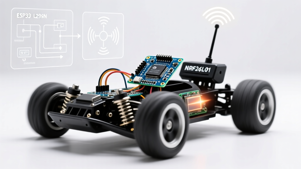
The most prevalent issue in any Arduino radio controlled car utilizing the popular 2.4GHz NRF24L01+ transceiver is the 'silent reset.' The car operates perfectly on the workbench, but the moment you place it on the track and apply full throttle, the steering locks up or the car drives in a straight line, ignoring transmitter inputs.
The Physics of the TX Burst Spike
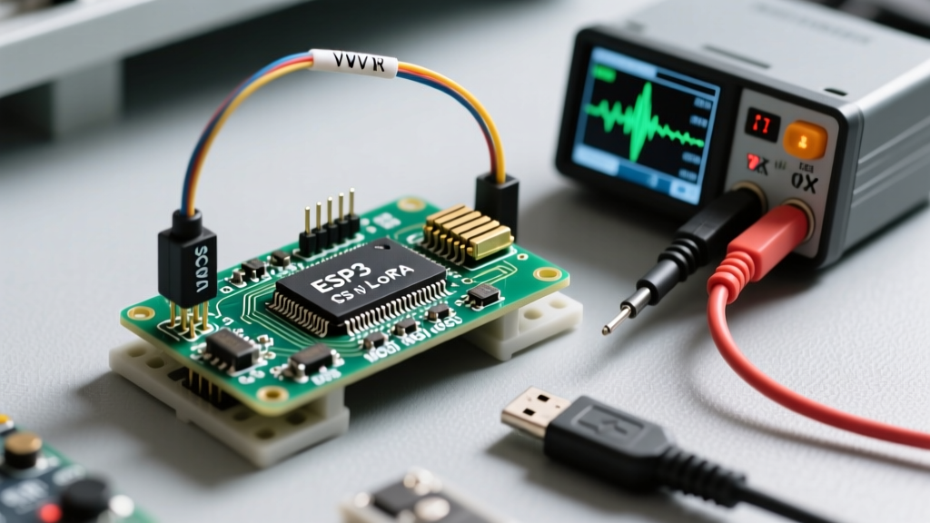
When the NRF24L01+PA+LNA (Power Amplifier/Low Noise Amplifier) variant switches from RX to TX mode to send an acknowledgment packet, it draws a transient current spike that can exceed 130mA for several microseconds. If your receiver Arduino is powered via the onboard 3.3V linear regulator (often an AMS1117-3.3 or, worse, the CH340G USB chip's internal 50mA regulator), this spike causes the 3.3V rail to sag below the ATmega328P's Brown-out Detection (BOD) threshold, typically set at 2.7V or 4.3V depending on the fuse bits.
Expert Diagnostic Tip: If your Arduino Nano's onboard 'L' LED (pin 13) rapidly flashes or resets every time the car hits a bump or accelerates, you are experiencing a BOD reset caused by RF transmission spikes, not a software crash.
The Definitive Hardware Fix
To stabilize the power delivery network (PDN) for the RF module, you must implement a dual-capacitor decoupling strategy directly at the module's VCC and GND pins. According to SparkFun's NRF24L01 Hookup Guide, high-frequency transceivers require both bulk energy storage and high-frequency noise filtering.
- Bulk Storage: Solder a 100µF low-ESR (Equivalent Series Resistance) electrolytic capacitor across the VCC and GND pins. This acts as a local energy reservoir to supply the 130mA TX spike without pulling from the main regulator.
- High-Frequency Filtering: Place a 0.1µF (100nF) ceramic capacitor in parallel with the electrolytic capacitor. Ceramic capacitors respond to nanosecond transient spikes that electrolytic capacitors are too slow to handle.
- Power Source: Never power the PA+LNA version directly from the Arduino's 3.3V pin. Use a dedicated 3.3V buck converter (like the AMS1117-3.3 mounted on a breakout board with adequate copper pour heatsinking) fed directly from the 2S LiPo battery's balance lead or main output.
2. Motor Driver Thermal Throttling and Voltage Sag
The second major point of failure in DIY RC cars is the motor driver. The ubiquitous L298N dual H-bridge module is heavily overrepresented in beginner kits, but it is fundamentally unsuited for modern, high-efficiency radio controlled cars due to its Bipolar Junction Transistor (BJT) architecture.
Why the L298N Fails Under Load
The L298N suffers from a massive internal voltage drop—typically between 2.0V and 2.5V at just 1A of current. If you are running a standard 2S LiPo battery (7.4V nominal, 8.4V fully charged), your 6V DC motors are only receiving roughly 5.4V to 5.9V under load. The remaining 2.5V is dissipated as pure heat (P = V × I). At 2A of stall current, the L298N is dissipating 5 Watts of heat. Because cheap clone modules lack proper heatsinks and thermal shutdown circuitry, the silicon junction overheats, causing the internal thermal protection to trip intermittently, resulting in 'stuttering' motors or complete shutdown mid-race.
The Modern Standard: TB6612FNG
For any serious Arduino radio controlled car build in 2026, the Toshiba TB6612FNG MOSFET Motor Driver is the undisputed gold standard. By utilizing MOSFETs instead of BJTs, the voltage drop is reduced to a mere 0.5V at 1A. This means your motors receive nearly the full battery voltage, resulting in higher top speeds, better torque, and drastically reduced heat generation.
| Specification | L298N (Legacy BJT) | TB6612FNG (MOSFET) | DRV8833 (MOSFET) |
|---|---|---|---|
| Continuous Current per Ch | 2.0A | 1.2A (3.2A peak) | 1.5A (2.0A peak) |
| Voltage Drop (at 1A) | ~2.0V - 2.5V | ~0.5V | ~0.4V |
| PWM Switching Frequency | Up to 25 kHz | Up to 100 kHz | Up to 50 kHz |
| Thermal Shutdown | Rarely on clones | Yes (Internal) | Yes (Internal) |
| Logic Level Voltage | 5V (Requires level shift) | 2.7V - 5.5V | 2.7V - 10.8V |
3. SPI Bus Degradation and RF Packet Drops
If your Arduino radio controlled car experiences severe range limitations or 'jittery' servo control at distances beyond 10 meters, the issue is rarely the RF module itself. It is almost always Signal Integrity (SI) degradation on the Serial Peripheral Interface (SPI) bus connecting the ATmega328P to the NRF24L01.
The Dupont Wire Antenna Problem
The SPI bus operates at high frequencies (typically 8MHz to 16MHz on default Arduino configurations). When you use standard 20cm female-to-female Dupont jumper wires to connect the SCK, MOSI, MISO, and CSN pins, those wires act as unshielded transmission lines. At 16MHz, a 20cm wire approaches a quarter-wavelength, causing severe signal reflections, crosstalk, and electromagnetic interference (EMI) from the nearby DC motors.
Software and Hardware Mitigations
To diagnose and fix SPI-related packet loss, implement the following protocol adjustments:
- Reduce SPI Clock Speed: In your setup() function, force the SPI clock divider down to 4MHz. This drastically improves signal integrity over longer, unshielded wires.
SPI.setClockDivider(SPI_CLOCK_DIV4); - Wire Routing: Keep SPI traces or wires under 5cm. If you must route them further, use twisted-pair wiring (twisting the SCK wire with a GND wire) to minimize inductive loop area.
- Motor EMI Shielding: Solder 0.1µF ceramic capacitors directly across the terminals of your DC brushed motors, and from each terminal to the motor's metal casing. This suppresses the broadband RF noise generated by the motor brushes, which otherwise desensitizes the receiver's LNA.
4. Software Latency: Escaping the Blocking Loop
A common symptom in advanced RC builds is 'steering lag'—the car continues to turn for a fraction of a second after you center the transmitter joystick. This is rarely a hardware fault; it is a software architecture flaw caused by blocking code.
Many makers utilize the delay() function or rely on blocking I2C sensor reads (such as polling an MPU6050 gyroscope for traction control) inside the main loop(). According to the Arduino Official Power and Timing Documentation, any blocking call halts the microcontroller's ability to read incoming RF payloads or update PWM signals to the steering servo.
Implementing Non-Blocking Telemetry
To achieve sub-10ms control latency, your receiver code must be entirely event-driven and non-blocking. Replace all delay() calls with a millis() based state machine.
Furthermore, if your RC car uses an I2C IMU for stability control, do not use the standard Wire.h library in its default blocking mode. Either implement hardware interrupts to read the IMU's FIFO buffer only when new data is ready, or utilize a DMA-enabled I2C library to prevent the CPU from stalling while waiting for I2C clock stretching.
Summary Diagnostic Checklist
Before tearing apart your Arduino radio controlled car's wiring harness, run through this rapid diagnostic checklist:
- Symptom: Car resets when throttle is applied. Fix: Add 100µF + 0.1µF capacitors to RF module; check LiPo C-rating (ensure >30C to prevent main voltage sag).
- Symptom: Motors whine but don't turn, or driver gets hot. Fix: Replace L298N with TB6612FNG; verify PWM frequency is at least 20kHz to move motor whine out of audible range.
- Symptom: Range drops from 50m to 5m. Fix: Shorten SPI wires; add 0.1µF decoupling to motor terminals; lower SPI clock to 4MHz.
- Symptom: Steering feels sluggish or delayed. Fix: Audit code for
delay()or blockingWire.requestFrom()calls; implementmillis()timing.
By addressing these specific power, thermal, and signal integrity bottlenecks, you transform a fragile breadboard prototype into a robust, competition-ready radio controlled vehicle capable of handling the extreme electrical noise and physical vibrations of off-road RC racing.