
The Dual Nature of Arduino Header Errors
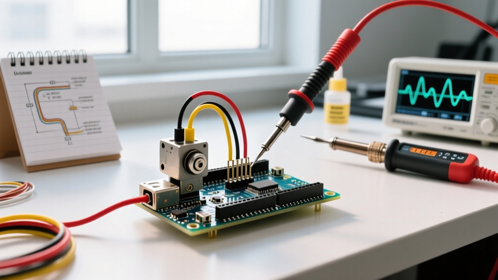
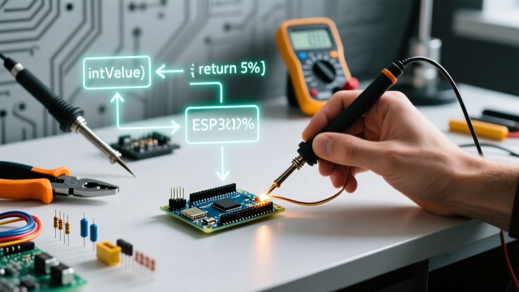
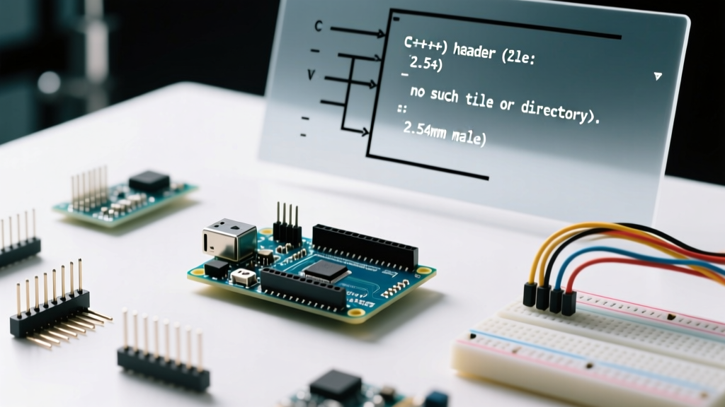
When makers and embedded engineers encounter an 'Arduino header' error, the diagnosis is often delayed by a fundamental ambiguity in terminology. In the microcontroller ecosystem, the term 'header' refers to two entirely distinct domains: the physical 2.54mm (0.1-inch) pitch pin headers soldered to the PCB, and the C++ .h header files required for sketch compilation. A failure in either domain will halt your project, but the symptoms, diagnostic tools, and resolutions are vastly different.
As of 2026, with the widespread adoption of the Arduino IDE 2.x and PlatformIO environments, alongside the release of newer boards like the Uno R4 Minima and Nano ESP32, understanding the precise failure modes of both hardware pins and software includes is critical. This guide provides an expert-level diagnostic framework to isolate and resolve both physical and compilation-based Arduino header errors.
Hardware Diagnosis: Physical 2.54mm Header Pin Faults
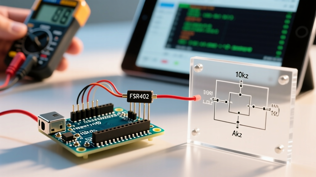
Physical headers on boards like the classic Uno R3 or Mega 2560 consist of female 1x15, 1x10, and 1x8 receptacles, alongside the 2x3 ICSP (In-Circuit Serial Programming) header. Hardware header errors typically manifest as upload failures, erratic sensor readings, or sudden brownout resets.
1. The 'Programmer Not Responding' Upload Failure
The most infamous hardware error linked to physical headers is the avrdude: stk500_recv(): programmer is not responding message. While often blamed on the bootloader, this is frequently caused by a physical fault on the Digital 0 (RX) and Digital 1 (TX) header pins.
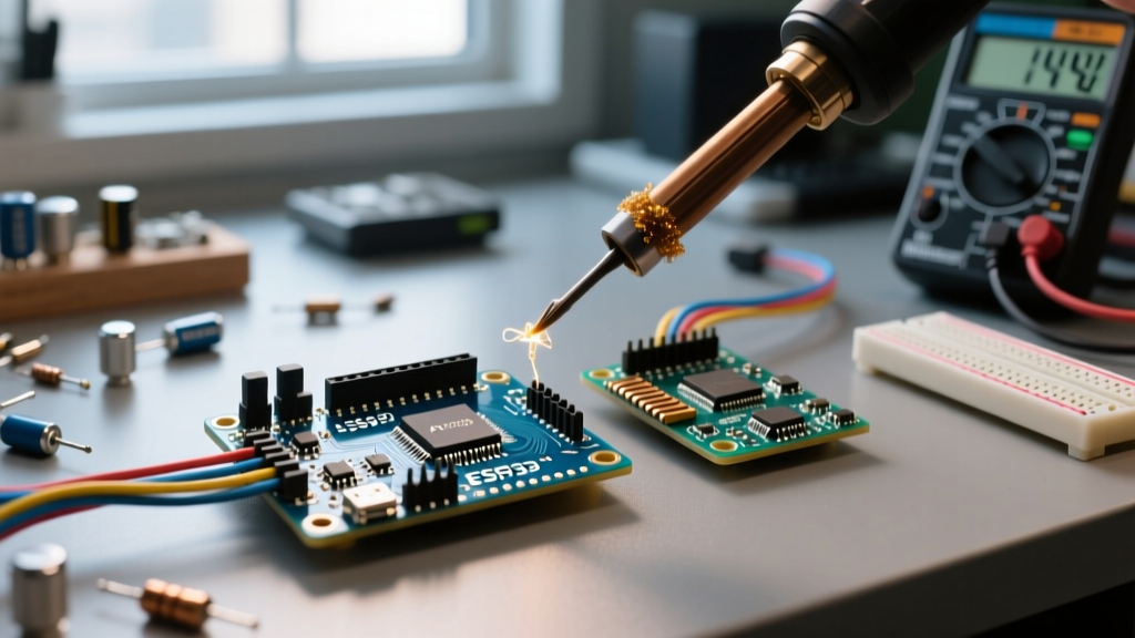
- Solder Bridge Shorts: Excessive solder wicking between the RX/TX header pads and the adjacent GND pad can create a high-resistance short. This pulls the UART lines low, preventing the ATmega16U2 (or CH340G on clones) from establishing serial handshakes.
- ICSP Header Misalignment: If you are using an external ISP programmer (like the USBasp or Atmel ICE), a misaligned 2x3 ICSP header connection will reverse the MISO/MOSI lines or feed 5V directly into the reset pin, causing immediate communication failure.
- DTR Auto-Reset Capacitor Failure: On Nano and Pro Mini boards, the 0.1µF ceramic capacitor linking the DTR line to the reset header pin often cracks due to mechanical stress when inserting tight jumper wires. If this capacitor fails open, the board will compile but fail to auto-reset during upload.
2. Power Header Instability and Brownouts
The 5V and GND header pins carry the bulk of the current for external shields. A cold solder joint on the 5V header pin will introduce parasitic resistance. Under a 200mA load (e.g., driving a small OLED and a servo), the voltage at the shield's header can drop below 4.2V. The ATmega328P's Brownout Detection (BOD) is typically factory-set to 4.3V, triggering an immediate, silent reset loop. Diagnose this by measuring the voltage directly across the shield's male header pins under load, rather than at the board's USB port.
Software Diagnosis: C++ Header File Compilation Faults
On the software side, header files (.h) instruct the C++ preprocessor on how to link libraries, define macros, and declare functions. Compilation errors here are strict and unforgiving.
1. The Missing 'Arduino.h' Fatal Error
If you are migrating from the Arduino IDE to a professional environment like Visual Studio Code with PlatformIO, or writing custom C++ classes, you will inevitably encounter: fatal error: Arduino.h: No such file or directory.
This occurs because the Arduino IDE automatically injects #include <Arduino.h> into the main .ino sketch file behind the scenes. However, standard C++ compilers require explicit inclusion. If you create a custom MySensor.cpp and MySensor.h file, you must manually place #include <Arduino.h> at the top of your custom header file to grant it access to core functions like digitalWrite() and millis().
2. Circular Dependencies and Multiple Definitions
As projects scale, you may encounter multiple definition of linker errors. This happens when Header A includes Header B, and Header B includes Header A, creating an infinite inclusion loop, or when a function is defined (not just declared) inside a header file that is included in multiple .cpp files.
The Fix: Always use include guards. While #pragma once is widely supported in modern GCC/AVR-GCC toolchains, the traditional #ifndef guard remains the safest standard for cross-platform compatibility.
Expert Tip: Never place executable code or variable definitions directly in a
.hfile unless they are markedinlineorconst. Use the header file strictly for declarations, and reserve the.cppfile for the actual implementation logic.
Diagnostic Matrix: Hardware vs. Software Header Faults
| Symptom / Error Message | Domain | Root Cause | Actionable Resolution |
|---|---|---|---|
| avrdude: stk500_recv() programmer not responding | Hardware | RX/TX header short or broken DTR capacitor | Test D0/D1 continuity to GND; replace 0.1µF reset cap. |
| Board resets randomly when shield is attached | Hardware | 5V header cold joint causing voltage drop below BOD | Reflow 5V/GND header pins with flux; measure under load. |
| fatal error: Arduino.h: No such file or directory | Software | Missing core include in custom .cpp/.h files | Add #include <Arduino.h> to the top of custom headers. |
| multiple definition of `setup()' or custom function | Software | Function defined in .h file included in multiple sources | Move implementation to .cpp; use #ifndef include guards. |
| Library not found / Wire.h missing | Software | IDE library path corruption or PlatformIO env mismatch | Reinstall via Library Manager; verify lib_deps in platformio.ini. |
Advanced Diagnostic Tools for the 2026 Workbench
To move beyond guesswork, professional embedded debuggers rely on specific instrumentation to validate both physical and logical header integrity.
- USB Logic Analyzers: Tools like the Saleae Logic 8 (approx. $119) or budget DSLogic Plus alternatives are indispensable for clipping onto the D0/D1 and ICSP headers. If the physical pins are intact but the bootloader is corrupted, a logic analyzer will reveal the UART handshake attempts failing at the baud rate level (typically 115200 or 19200 for Optiboot).
- Thermal Imaging Cameras: When a physical header solder bridge causes a micro-short between VCC and an I/O pin, the ATmega chip or the linear voltage regulator will heat up. A FLIR ONE or InfiRay P2 thermal camera can instantly highlight the exact shorted header pin by detecting the localized thermal bloom.
- PlatformIO Dependency Graph: For software header nightmares, use the
pio pkg treecommand in the PlatformIO CLI. This generates a visual map of all included header files and library dependencies, instantly exposing circular references or conflicting library versions (e.g., two different I2C libraries attempting to redefine theWire.hhardware buffer).
Authoritative References and Further Reading
For deep dives into standard library structures and hardware specifications, consult the official documentation. The Arduino Library Specification provides the definitive rules on how the compiler parses header files and folder structures. Additionally, the Arduino Libraries Guide offers excellent foundational advice on managing include paths and avoiding namespace collisions in complex sketches. For hardware pinout and electrical characteristics, always refer to the specific board's schematic and the Arduino Language Reference to ensure your header manipulations remain within the safe operating area of the microcontroller.