
The Hidden Bottleneck: Why Standard Prototyping Wires Fail
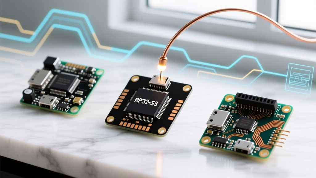
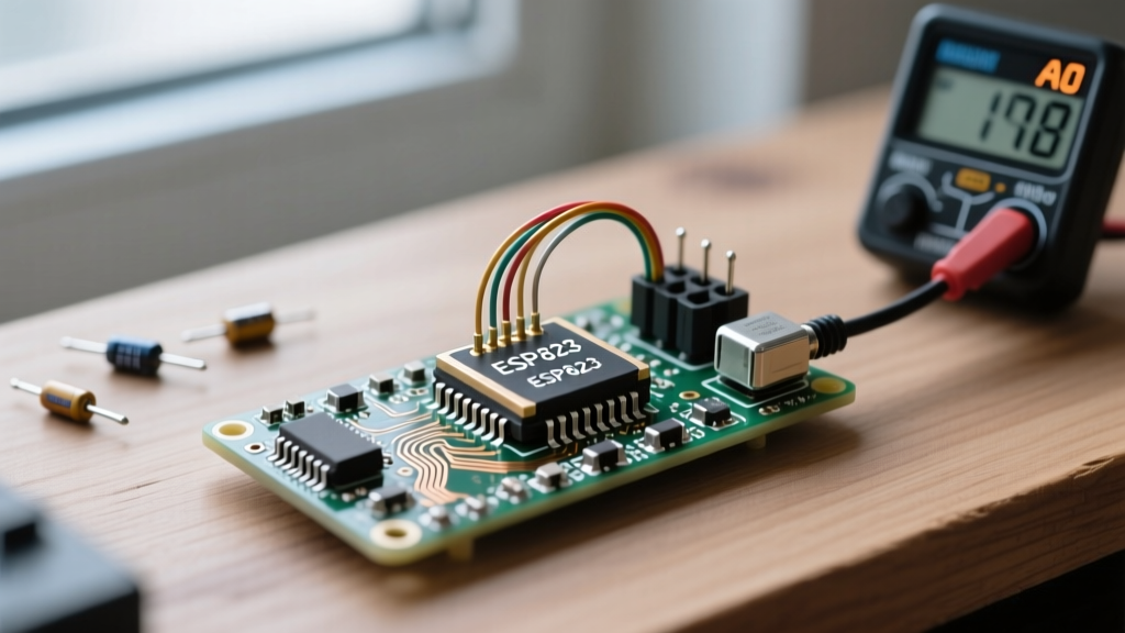
Every maker starts with a breadboard and a handful of colorful Dupont-style cables. They are cheap, accessible, and perfect for blinking an LED or testing a basic sensor. However, as projects evolve from weekend prototypes into permanent, field-deployed installations, the physical limitations of these cables become a critical point of failure. When upgrading your jumper wires Arduino setups for modern microcontrollers like the ESP32-S3 or the Raspberry Pi RP2350, relying on standard 28 AWG tin-plated strands is a recipe for intermittent brownouts, I2C bus crashes, and high-frequency signal degradation.
This migration guide outlines the engineering realities of prototyping wires, provides a diagnostic framework for identifying when to upgrade, and details the exact tools and connectors needed to transition to professional-grade wiring harnesses in 2026.
Expert Insight: A standard 20cm Dupont jumper wire has a contact resistance of roughly 20mΩ to 50mΩ per connection point. On a 5V rail powering a servo or high-draw sensor array, passing 1.5A through four of these connections (breadboard to wire, wire to header) can introduce a voltage drop of over 300mV. This easily pushes a 5.0V line below the 4.5V brownout threshold of an ATmega328P, causing silent resets.
Diagnostic Checklist: When to Migrate Away from Breadboard Jumpers
Before tearing down your prototype, verify if your current wiring topology is the root cause of your system's instability. Look for these specific failure modes:
- I2C ACK Errors & Bus Lockups: The I2C specification limits bus capacitance to 400pF. Standard untwisted jumper wires add roughly 1.5pF to 2.5pF per inch. A complex sensor array using long, parallel jumper runs can easily exceed this capacitance, rounding off the square wave edges and causing communication timeouts at 400kHz.
- SPI Clock Skew & Ghost Data: Modern MCUs push SPI clocks well past 20MHz. Long, untwisted jumper wires act as antennas, introducing crosstalk between the MOSI and MISO lines, leading to corrupted data payloads.
- Vibration-Induced Intermittency: Dupont connectors rely on simple leaf-spring friction. In any environment with mechanical vibration (robotics, automotive, motorized enclosures), these pins will micro-disconnect, causing SPI drops or encoder miscounts.
- Thermal Droop on Power Rails: If the plastic housing of your jumper wire feels warm, or if the 5V/3.3V rail sags when peripherals activate, the 28 AWG wire and undersized brass contacts are choking the current flow.
The 2026 Upgrade Matrix: Comparing Wiring Solutions
Migrating away from loose jumpers doesn't mean you must immediately design a custom PCB. The industry standard for intermediate-to-advanced MCU deployments involves discrete crimped harnesses. Below is a comparison of the most reliable interconnect systems available today.
| Connector System | Pitch | Optimal AWG | Current Rating | Vibration Resist. | Best Use Case |
|---|---|---|---|---|---|
| Dupont (Standard) | 2.54mm (0.1") | 28 AWG | 1A - 3A | Very Low | Breadboard prototyping only |
| JST XH Series | 2.50mm | 24 - 28 AWG | 3A (24 AWG) | High | Sensor arrays, battery packs, general I/O |
| Molex KK 254 | 2.54mm (0.1") | 22 - 30 AWG | 2.5A - 4A | Very High (Friction Lock) | Industrial control, high-vibration robotics |
| IDC Ribbon (TCSD) | 2.54mm (0.1") | 28 AWG Flat | 1A per line | Moderate | Parallel buses, LCD screens, multi-pin headers |
| JST PH Series | 2.00mm | 26 - 30 AWG | 2A | High | Compact drones, wearable MCUs, space-constrained builds |
Step-by-Step Migration: Transitioning to JST XH and Molex KK 254
To build reliable harnesses, you must abandon pre-crimped wires and learn to crimp your own using high-quality silicone stranded wire. Silicone insulation is highly flexible, heat-resistant (up to 200°C), and prevents the 'stiff wire' memory effect that plagues standard PVC wiring.
1. Procure the Correct Tooling
Do not use standard needle-nose pliers. A proper ratcheting crimper ensures a gas-tight mechanical and electrical bond. For JST XH and Molex KK 254 terminals, the IWISS SN-28B or the Engineer PA-09 are the industry-standard ratcheting crimpers for hobbyists and low-volume production. Expect to invest between $35 and $55 for a genuine ratcheting tool.
2. Select the Right Wire Gauge
For standard I2C, SPI, and GPIO signal lines, 26 AWG stranded silicone wire is optimal. It offers a massive reduction in resistance compared to 28 AWG while still fitting neatly into 2.54mm connector housings. For power rails (5V, 12V, 24V) driving motors or high-power LED matrices, step up to 22 AWG or 20 AWG and use Molex KK 254 connectors, which accept thicker gauges.
3. The Crimping Workflow
- Strip the Wire: Use a precision wire stripper to remove exactly 2.5mm to 3.0mm of insulation. Exposing too much bare wire will cause shorts when inserted into the housing; too little will result in a weak crimp on the insulation grip.
- Position the Terminal: Insert the terminal into the crimper's jaw. The SN-28B has specific notches for the conductor crimp and the insulation crimp.
- Pre-Crimp: Squeeze the handle just enough to hold the terminal in place.
- Insert and Finish: Slide the stripped wire into the terminal until the strands hit the front bell. Squeeze the ratchet fully until it releases. The ratcheting mechanism guarantees the exact compression force required by the terminal manufacturer.
- Seat the Pin: Push the crimped terminal into the plastic housing until you hear and feel a definitive 'click' from the retention barb.
Advanced Signal Integrity: Managing High-Speed MCU Buses
As microcontrollers continue to push higher clock speeds, the physical wiring topology becomes just as important as the code. According to SparkFun's connector basics tutorial, understanding the mechanical and electrical limits of your interconnects is vital for high-speed data. If you are migrating an I2C bus that spans more than 30 centimeters, standard jumper wires will fail.
Overcoming I2C Capacitance Limits
If your oscilloscope shows rounded, shark-fin-like waveforms on the SDA and SCL lines, your bus capacitance is too high. To fix this during your wiring migration:
- Switch to 28 AWG twisted pair specifically manufactured for I2C (often sold with integrated ground drains).
- Lower your I2C pull-up resistors from the standard 4.7kΩ down to 2.2kΩ or even 1.5kΩ. This provides a stronger current source to charge the parasitic capacitance of the longer wires faster, restoring sharp square-wave edges.
- Use an I2C bus extender IC (like the PCA9600 or PCA9615) which converts the I2C protocol to a differential signal capable of traveling meters over standard CAT5/6 ethernet cable.
Securing Connections in the Field
For permanent installations where the MCU will be mounted inside an enclosure subject to thermal expansion and contraction, friction-fit headers are insufficient. Adafruit's comprehensive crimping guide highly recommends utilizing connectors with positive locking mechanisms. The Molex KK 254 series features a 'friction lock' ramp on the housing that physically snaps over a tab on the male PCB header. This ensures that even if the wire is pulled or subjected to extreme thermal cycling, the electrical contact remains unbroken.
Frequently Asked Questions (FAQ)
Can I just solder jumper wires directly to the Arduino headers?
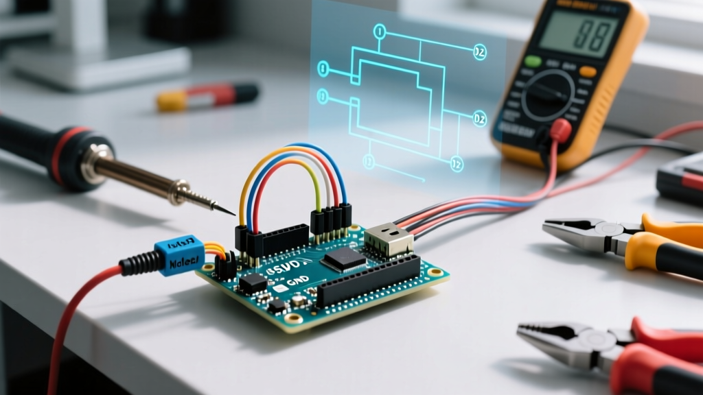
While direct soldering eliminates contact resistance, it creates a massive mechanical vulnerability. A single bend or pull on a stiff PVC jumper wire will transfer leverage directly to the PCB pad, eventually lifting the pad off the Arduino's fiberglass substrate. Always use a strain-relieved connector system or hot-glue/RTV silicone to anchor the wires to the board edge if direct soldering is unavoidable.
Are gold-plated jumper wires worth the premium?
Gold plating (typically 10-30 microinches) prevents oxidation and ensures low contact resistance over years of use. However, for indoor, climate-controlled environments, standard tin-plated brass terminals (like genuine JST or Molex) are perfectly adequate and cost 80% less. Reserve gold-plated terminals for harsh, high-humidity, or outdoor IoT deployments.
How do I transition a breadboard prototype to a perfboard with these new connectors?
Purchase male-header versions of your chosen connector (e.g., JST XH right-angle male headers). Solder these directly to the copper pads of a standard 2.54mm perfboard or protoboard. This creates a robust 'breakout' hub where your newly crimped, professional-grade silicone harnesses can plug securely into your permanent MCU circuit.