
Beyond the Chip: Defining the Arduino Circuit Board
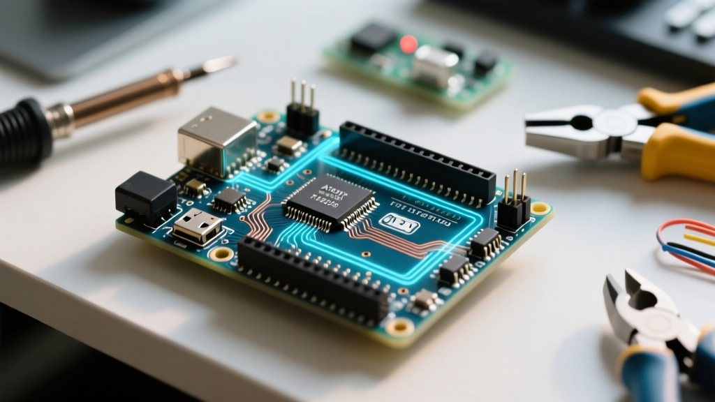
When makers and engineers refer to an "Arduino," they are rarely talking about the microcontroller chip itself. Instead, they are referencing the Arduino circuit board—a highly engineered printed circuit board (PCB) that transforms a bare silicon die into an accessible, robust development platform. As of 2026, the transition from legacy 8-bit AVR architectures to 32-bit ARM and RISC-V ecosystems has fundamentally changed the component density and power management strategies on these boards.
Understanding the physical and electrical anatomy of an Arduino circuit board is critical for debugging complex hardware failures, designing custom shields, and managing power budgets in embedded IoT deployments. This guide deconstructs the substrate, silicon, and support circuitry that define modern Arduino hardware.
The PCB Substrate: Material Science and Layer Stackup
The foundation of any Arduino circuit board is the PCB substrate. Standard boards like the Uno R4 Minima and Nano ESP32 utilize FR-4 (Flame Retardant 4) glass-reinforced epoxy laminate. This material provides a dielectric constant of roughly 4.5, which is sufficient for the sub-100MHz digital signaling typical of most maker projects.
- Thickness: Standardized at 1.6mm, providing the mechanical rigidity required to withstand the insertion force of jumper wires and shield stacking headers.
- Copper Weight: Typically 1 oz/ft² (approx. 35µm thick). This allows standard signal traces to handle up to 0.5A continuously, while wider power planes can safely route 2A to 3A without excessive thermal rise.
- Surface Finish: While older through-hole boards used HASL (Hot Air Solder Leveling), modern surface-mount Arduino boards increasingly use ENIG (Electroless Nickel Immersion Gold). ENIG provides a flat surface necessary for the fine-pitch QFN and BGA packages found on modern ESP32 and Renesas chips.
For a deeper understanding of how these materials influence signal integrity and manufacturing, SparkFun's PCB Basics guide offers an excellent primer on trace routing and substrate selection.
The Brain: Microcontroller Architecture Evolution
The microcontroller unit (MCU) is the central processing node of the Arduino circuit board. The landscape has shifted dramatically from the classic 8-bit era to modern 32-bit heterogeneous computing.
| Board Model (2026 Standard) | Core MCU | Architecture | Clock Speed | Flash / SRAM | Typical Price |
|---|---|---|---|---|---|
| Uno R3 (Legacy) | ATmega328P | 8-bit AVR | 16 MHz | 32 KB / 2 KB | $15 - $20 |
| Uno R4 Minima | Renesas RA4M1 | 32-bit ARM Cortex-M4 | 48 MHz | 256 KB / 32 KB | $20 - $24 |
| Nano ESP32 | ESP32-S3 | 32-bit Xtensa LX7 (Dual-Core) | 240 MHz | 8 MB (Ext) / 512 KB | $26 - $30 |
The shift to the Renesas RA4M1 on the Uno R4 introduced a floating-point unit (FPU) and a 12-bit DAC directly on the official Uno R4 hardware architecture, eliminating the need for external digital-to-analog conversion chips in audio and precision control projects.
Power Management: LDOs, Buck Converters, and Protection
Power delivery is where the Arduino circuit board faces its most severe thermal and electrical stresses. A board must accept unregulated input from a barrel jack or USB, step it down to 5V and 3.3V, and protect the host PC from downstream shorts.
The Voltage Regulator Dilemma
On legacy boards, a linear Low Dropout (LDO) regulator (like the NCP1117-5.0) handled the barrel jack input. Linear regulators dissipate excess voltage as heat. If you supply 12V to the Vin pin and draw 200mA for a sensor shield, the LDO must dissipate (12V - 5V) * 0.2A = 1.4 Watts. Without a heatsink, the SOT-223 package will quickly hit its 125°C thermal shutdown threshold.
Modern boards have largely migrated to switching buck converters for high-voltage inputs, which operate at 85-90% efficiency, virtually eliminating thermal throttling at higher input voltages. However, the 5V-to-3.3V rail often still relies on an LDO, as the current draw for 3.3V logic is generally lower and the voltage drop (1.7V) is thermally manageable.
USB Protection and Power Multiplexing
Every genuine Arduino circuit board includes a PTC (Positive Temperature Coefficient) resettable polyfuse on the USB VBUS line. Typically rated at 500mA, this component protects your computer's USB port. If a short circuit occurs on your breadboard, the PTC heats up, its resistance spikes to several hundred ohms, and the current drops to a safe trickle. Once the fault is removed and the component cools, it resets automatically.
Clock Generation: The Heartbeat of the Board
Microcontrollers require a precise clock signal to execute instructions and manage serial communication. While many modern MCUs feature internal RC oscillators, these can drift by 2% to 5% over temperature variations. This drift is catastrophic for hardware UART, causing baud rate mismatches and corrupted data packets.
To solve this, the Arduino circuit board integrates an external quartz crystal oscillator (typically a 16MHz ABM8G surface-mount crystal). These crystals are laser-trimmed to a tolerance of ±10ppm (parts per million), ensuring that serial communication at 115,200 baud remains perfectly synchronized with host PCs and peripheral modules.
USB-to-Serial Interfacing
Early Arduino designs required a dedicated secondary chip (like the ATmega16U2 or FT232RL) to bridge the gap between the PC's USB protocol and the MCU's UART serial pins. Today, boards like the Nano ESP32 feature native USB peripherals built directly into the main silicon. As detailed in the Nano ESP32 documentation, native USB allows the board to emulate HID devices (keyboards, mice) and MIDI controllers without the latency and bottleneck of a secondary serial bridge chip.
Common PCB Failure Modes and Expert Troubleshooting
Even with robust protection circuitry, Arduino circuit boards can fail under specific edge cases. Below is a diagnostic matrix for common hardware-level faults encountered in the field.
| Symptom | Probable Root Cause | Diagnostic Step | Component-Level Fix |
|---|---|---|---|
| Board dead via USB, works on Barrel Jack | Blown PTC Polyfuse or damaged USB VBUS trace | Measure continuity across the PTC; check for 5V at the USB connector pins. | Replace the surface-mount PTC with a 500mA Bourns MF-MSMF series fuse. |
| "Magic Smoke" or extreme heat near power jack | Vin overvoltage (>12V) causing LDO thermal runaway | Inspect the NCP1117 LDO for bulging; test input diode for short. | Desolder dead LDO; replace with a high-efficiency 5V buck module wired to the 5V pin. |
| Erratic ADC readings and serial dropouts | Compromised ground plane or lifted USB shield ground | Check resistance between USB shell and main GND pin (should be < 1Ω). | Resolder USB connector shield pins; add a 100nF decoupling cap near the MCU VCC. |
| MCU fails to enter bootloader mode | Corrupted bootloader or damaged reset capacitor | Check the 100nF capacitor between the DTR line and the RESET pin. | Replace capacitor; re-flash bootloader via ICSP header using an external programmer. |
Expert Warning on Backfeeding: Never inject 5V into the "5V" pin while the USB cable is simultaneously connected to a PC, unless your specific board features an active power-path management IC. On older or clone boards lacking proper Schottky isolation, backfeeding can force 5V directly into the PC's USB data lines or the secondary USB-Serial chip, permanently destroying the host motherboard's USB controller.
Designing for the Future: Shield Compatibility
As the Arduino circuit board evolves to support higher clock speeds and Wi-Fi/BLE radios, the physical footprint remains remarkably consistent. The 0.1-inch (2.54mm) header spacing ensures that a shield designed for the 2012 Uno R3 will physically mate with a 2026 Uno R4. However, electrical compatibility requires careful attention to logic levels. While legacy boards operate at 5V logic, modern 32-bit boards often utilize 3.3V logic. Makers must now integrate bidirectional level shifters (like the NXP PCA9306) on their custom shields to prevent overvoltage damage to the MCU's GPIO pins.
Summary
The Arduino circuit board is far more than a breakout board for a microcontroller. It is a carefully balanced ecosystem of power regulation, precise timing, and protective circuitry designed to bridge the gap between fragile silicon and the messy reality of physical computing. By understanding the substrate materials, power architectures, and failure modes detailed above, engineers can design more reliable embedded systems and troubleshoot hardware faults with surgical precision.