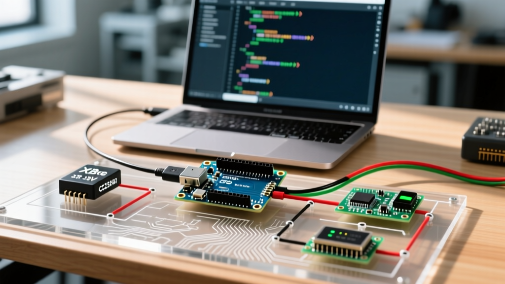

The Core Challenge: 5V Logic vs. 3-Phase High Current
Interfacing a brushless motor with Arduino is a rite of passage for robotics and drone enthusiasts, but it fundamentally differs from driving standard brushed DC motors. A standard Arduino GPIO pin can safely source or sink only about 20mA to 40mA at 5V. Conversely, a typical hobbyist Brushless DC (BLDC) motor requires 15A to 30A at 11.1V to 14.8V, distributed across three distinct phases.
You cannot connect a BLDC motor directly to an Arduino, nor can you use a standard L298N H-Bridge motor driver. H-bridges are designed for single-phase commutation (reversing polarity). BLDC motors require electronic commutation—the precise, timed firing of three separate half-bridges to create a rotating magnetic field. This is where the Electronic Speed Controller (ESC) becomes mandatory.
How Sensorless ESCs and Back-EMF Work
Most hobby ESCs paired with Arduino projects are 'sensorless.' Unlike industrial BLDC motors that use physical Hall-effect sensors to report rotor position, hobby motors rely on the ESC to deduce rotor position dynamically.
The ESC achieves this by monitoring Back-Electromotive Force (Back-EMF). As the permanent magnets on the rotor spin past the unpowered stator coil, they induce a small voltage. The ESC's microcontroller detects the 'zero-crossing' point of this induced voltage to calculate exactly when to fire the next phase. Because Back-EMF only exists when the motor is already moving, the ESC must 'blindly' pulse the motor to kickstart it before it can transition to closed-loop BEMF tracking. This is why BLDC motors often stutter or 'chirp' right before they begin spinning smoothly.
2026 Hardware Bill of Materials (BOM)
Component pricing and availability have stabilized as of 2026. Below is a reliable, tested hardware stack for a mid-power Arduino BLDC testbench.
| Component | Recommended Model | Key Specifications | Approx. Cost |
|---|---|---|---|
| Microcontroller | Arduino Uno R3 (or R4 Minima) | 5V Logic, 16MHz, PWM capable | $27.00 |
| Brushless Motor | Turnigy D2836/8 or EMAX CF2812 | 1100KV - 1534KV, 3-Phase | $19.50 |
| Speed Controller | Hobbywing Skywalker 40A ESC | 40A continuous, 5V/3A BEC, 50Hz PWM | $24.00 |
| Power Supply | ZIPPY Compact 3S LiPo | 11.1V, 2200mAh, 25C Discharge | $26.50 |
Wiring Matrix and the BEC Warning
Wiring an ESC requires strict attention to grounds and power isolation. The ESC features a thick power pair (for the battery) and a thin 3-wire servo lead (Signal, Ground, and 5V BEC).
Pinout Configuration
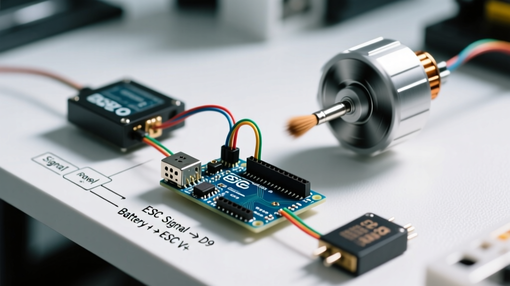
- ESC Signal (White/Yellow): Connect to Arduino Digital Pin 9 (Hardware PWM capable).
- ESC Ground (Black): Connect to Arduino GND. (A shared ground is non-negotiable for PWM signal reference).
- ESC VCC / BEC (Red): Outputs 5V. Leave disconnected if powering the Arduino via USB.
- ESC Power (Thick Red/Black): Connect to LiPo Battery via XT60 connector.
- Motor Phases (3 Wires): Connect to the ESC's 3 output wires. Order does not matter initially; swapping any two wires reverses the motor direction.
CRITICAL SAFETY WARNING: Never connect the ESC's red 5V BEC wire to the Arduino's 5V pin while the Arduino is simultaneously connected to your PC via USB. The USB 5V and the BEC 5V will back-feed into each other, potentially destroying the Arduino's onboard voltage regulator or your PC's USB port. Only use the BEC to power the Arduino in standalone, battery-only deployments.
The Arming Sequence: A Mandatory Handshake
The most common failure mode for beginners is a silent, unresponsive motor. ESCs are designed for RC aircraft safety and will not spin until they detect a valid 'zero-throttle' signal upon boot. This is called the Arming Sequence.
- Power on the Arduino and ensure it is outputting a 1000µs (0% throttle) PWM signal.
- Connect the LiPo battery to the ESC.
- The ESC will emit a startup tone (e.g., three ascending beeps indicating a 3S battery).
- After a 1-2 second delay, the ESC will emit a final confirmation beep, indicating it is armed and ready to accept throttle commands.
If you apply battery power before the Arduino boots and outputs the 1000µs signal, the ESC will interpret the floating pin as a safety hazard and enter an error state, typically indicated by rapid, continuous beeping.
Arduino Code Implementation
We utilize the standard Arduino Servo Library because ESCs expect the exact same 50Hz PWM protocol used by RC servos (a pulse every 20ms, with the pulse width varying from 1000µs to 2000µs).
#include <Servo.h>

Servo bldcESC;
const int escPin = 9;

void setup() {
  Serial.begin(9600);

  // Attach ESC and explicitly define the microsecond bounds
  // 1000µs = 0% throttle, 2000µs = 100% throttle
  bldcESC.attach(escPin, 1000, 2000);

  Serial.println("Sending 0% throttle to arm ESC...");
  bldcESC.writeMicroseconds(1000);

  // Wait for the ESC to complete its arming sequence
  delay(3000);
  Serial.println("ESC Armed. Spinning up...");
}

void loop() {
  // Ramp up to 20% throttle (approx 1200µs)
  bldcESC.writeMicroseconds(1200);
  delay(4000);

  // Drop back to idle
  bldcESC.writeMicroseconds(1000);
  delay(2000);
}
Why Use writeMicroseconds() Instead of write()?
While write(0) to write(180) works, it maps angles to pulse widths, introducing unnecessary mathematical abstraction and reducing resolution. Using writeMicroseconds() gives you exact 1-to-1 control over the PWM pulse width, which is vital for implementing smooth PID control loops in drone flight controllers or robotic actuators.
Advanced Troubleshooting and Edge Cases
Even with correct wiring, BLDC systems exhibit unique failure modes. Reference this diagnostic matrix to resolve common issues:
| Symptom | Root Cause | Solution |
|---|---|---|
| Motor stutters, vibrates, but won't spin | Incorrect phase timing or bad solder joint on one of the 3 motor wires. | Check continuity on all 3 phase wires. If using a programmable ESC, advance the timing via the programming card. |
| ESC emits continuous rapid beeps on boot | Throttle signal missing or above 1000µs during power-on. | Ensure Arduino is powered and outputting 1000µs before plugging in the LiPo battery. |
| Motor spins erratically at low throttle | Insufficient Back-EMF for the ESC's zero-crossing detector to track. | Implement a software 'ramp-up' in your code. Jump to 1150µs to break static friction, then settle to your target speed. |
| ESC overheats and cuts power (Thermal Cutoff) | Continuous amp draw exceeds ESC rating, or inadequate cooling airflow. | Downsize the propeller/load, or upgrade to an ESC with a 20% higher continuous amp rating than your calculated peak draw. |
Active Braking and Opto-Isolation
When you command an ESC to 0% throttle, it typically 'coasts'—the MOSFETs turn off, and the motor spins down naturally due to friction. In robotics, you often need immediate stopping. High-end ESCs (like those from Hobbywing or Castle Creations) support Active Braking (or Damped Light mode). This shorts the low-side MOSFETs together, turning the motor into a generator that rapidly dissipates its own kinetic energy as heat. Check your specific ESC manual to enable this via the programming card.
For industrial or high-voltage applications, consider using an Opto-isolated ESC. These models lack a BEC and use an optical isolator chip between the PWM input and the high-power MOSFET gate drivers. This completely eliminates ground loops and protects your sensitive Arduino logic from catastrophic voltage spikes caused by inductive kickback. For further reading on motor driver isolation and selection, the SparkFun Motor Driver Selection Guide provides excellent foundational architectures.
Summary
Successfully driving a brushless motor with Arduino hinges on understanding that the Arduino is not driving the motor directly; it is commanding a specialized 3-phase microcomputer (the ESC). By respecting the arming sequence, utilizing microsecond-precision PWM, and adhering to strict BEC isolation practices, you can reliably harness the immense power-to-weight ratio of BLDC motors in your 2026 robotics and automation projects.