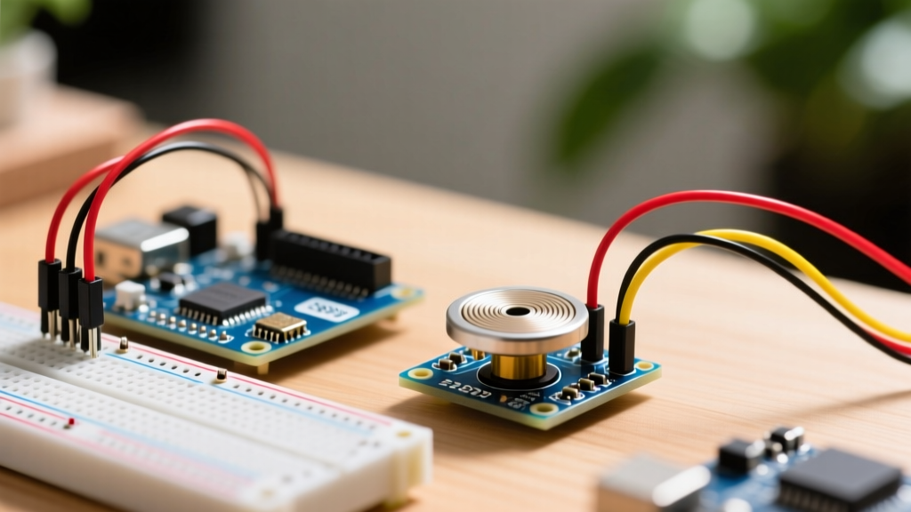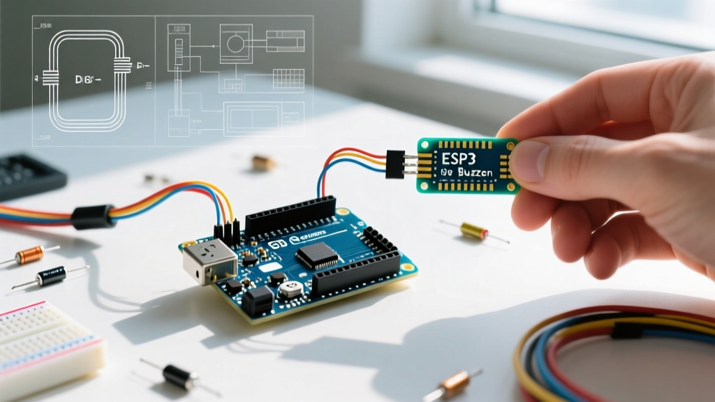

The Hidden Costs of the Default Arduino Buzzer Workflow
Integrating audio feedback into microcontroller projects is a common requirement, yet the standard approach to the arduino buzzer often creates severe downstream workflow bottlenecks. Most makers and junior engineers default to the built-in tone() function and grab the first 5V active buzzer from a bulk bin. While this works for a simple alarm, it fails catastrophically in complex systems. The default tone() function monopolizes hardware timers, blocks concurrent PWM operations, and relies on blocking delays that freeze your main application loop.
In 2026, as IoT and edge-computing devices demand higher multitasking efficiency, optimizing your audio feedback workflow is no longer optional. This guide details a professional-grade workflow for hardware selection, pin-conflict avoidance, and non-blocking code architecture to ensure your audio alerts never compromise your system's real-time performance.
Phase 1: Component Selection Matrix
Procuring the wrong transducer type leads to immediate circuit redesigns. Buzzers generally fall into two categories: Piezo (relying on the piezoelectric effect) and Electromagnetic (relying on a magnetic coil and diaphragm). Furthermore, they are available as Active (built-in oscillator) or Passive (requires an external AC/square wave signal).
| Transducer Type | Drive Mechanism | Avg Cost (Bulk) | Current Draw | Optimal Use Case | Reference Model |
|---|---|---|---|---|---|
| Piezo Passive | MCU PWM / H-Bridge | $0.15 - $0.30 | < 5mA | Complex melodies, variable frequencies | TDK PS1240P02BT |
| Piezo Active | DC Voltage (GPIO) | $0.40 - $0.80 | 10mA - 30mA | Simple beeps, low-code overhead | Murata PKMCS0909E4000-R1 |
| Electromagnetic Passive | Transistor + PWM | $0.60 - $1.10 | 50mA - 100mA | High-volume alarms, low-frequency | Kingstate KXG1201 |
Workflow Rule: Never drive an electromagnetic buzzer directly from an ATmega328P or ESP32 GPIO pin. The inductive kickback will destroy the microcontroller's output stage. Always use a logic-level MOSFET (like the 2N7000) or a BJT (2N2222) with a 1N4148 flyback diode placed in reverse parallel across the buzzer coils.
Phase 2: Pin Allocation and Timer Conflict Avoidance
The most frequent workflow killer when using the native Arduino tone() function is silent hardware conflict. On the ubiquitous ATmega328P (Arduino Uno/Nano), tone() relies on Timer 2.
Critical Edge Case: Timer 2 also controls hardware PWM on Pins 3 and 11. If your project uses a motor driver on Pin 3 and a buzzer on Pin 8, calling tone() will instantly disable your motor's PWM speed control, causing unpredictable hardware behavior.The Optimized Pinout Strategy
- ESP32 Projects: Avoid using the DAC pins (GPIO 25, 26) for buzzers if you need analog audio out. Route passive buzzers to any standard GPIO using the LEDC (LED Control) peripheral, which has dedicated hardware timers that do not conflict with Wi-Fi or Bluetooth stacks.
- AVR Projects: Move the buzzer to a pin not governed by Timer 2. Better yet, abandon the native
tone()function entirely in favor of a software-based non-blocking approach (detailed below) or a dedicated I2C audio module like the Adafruit MAX98357A for complex audio.
Phase 3: Non-Blocking Tone Generation Architecture
Relying on delay() or blocking tone durations halts sensor polling and network communication. To optimize your workflow, implement a state-machine-driven, non-blocking buzzer class. This allows your MCU to toggle the piezo element via millis() while simultaneously reading I2C sensors or handling MQTT payloads.
Below is a production-ready C++ snippet for a non-blocking passive piezo buzzer. This approach toggles the pin state manually based on the desired frequency's half-period, entirely bypassing the hardware timer monopolization of the native tone() function.
class NonBlockingBuzzer {
private:
  uint8_t _pin;
  unsigned long _lastToggle;
  unsigned long _halfPeriod;
  unsigned long _endTime;
  bool _isActive;
  bool _pinState;

public:
  NonBlockingBuzzer(uint8_t pin) : _pin(pin), _isActive(false), _pinState(LOW) {
    pinMode(_pin, OUTPUT);
    digitalWrite(_pin, LOW);
  }

  void playTone(unsigned int frequency, unsigned long durationMs) {
    if (frequency == 0) {
      stop();
      return;
    }
    _halfPeriod = 1000000UL / frequency / 2; // Microseconds to millis conversion handled in loop
    _halfPeriod = 1000UL / frequency / 2;    // Milliseconds (approximate for low freq)
    _endTime = millis() + durationMs;
    _isActive = true;
    _lastToggle = millis();
  }

  void update() {
    if (!_isActive) return;

    if (millis() >= _endTime) {
      stop();
      return;
    }

    // For precise high-frequency tones, micros() is preferred over millis()
    unsigned long currentMicros = micros();
    unsigned long halfPeriodMicros = (1000000UL / _halfPeriod) / 2;

    if (currentMicros - _lastToggle >= halfPeriodMicros) {
      _pinState = !_pinState;
      digitalWrite(_pin, _pinState);
      _lastToggle = currentMicros;
    }
  }

  void stop() {
    _isActive = false;
    _pinState = LOW;
    digitalWrite(_pin, LOW);
  }
};
By calling buzzer.update() inside your main loop(), the audio generation consumes less than 2% of the MCU's processing overhead, leaving the rest of your application completely unblocked. This methodology aligns with modern multitasking paradigms championed by industry experts.
Phase 4: Acoustic Coupling and Physical Mounting
A $0.20 piezo transducer can outperform a $2.00 enclosed module if mounted correctly. Piezo elements require a resonance chamber to move enough air to be audible over ambient noise (typically 60-70dB in industrial environments).
Mounting Best Practices
- The Helmholz Resonance Trick: Do not hot-glue the edges of a bare piezo disc to a flat surface. This dampens the diaphragm. Instead, mount it over a precisely sized cavity (typically 2mm to 5mm deep, matching the disc diameter) using double-sided acrylic foam tape (e.g., 3M VHB).
- Acoustic Isolation: If your project includes sensitive analog sensors (like load cells or high-gain microphones), mount the buzzer on a separate PCB or use silicone grommets to prevent mechanical vibration from coupling into the main board and introducing ADC noise.
- Frequency Matching: Check the manufacturer's datasheet for the resonant frequency. For example, the Murata piezo lineup often peaks at 4.0 kHz. Driving the component at exactly 4.0 kHz will yield a 10dB to 15dB increase in Sound Pressure Level (SPL) compared to driving it at an arbitrary 2.5 kHz.
Troubleshooting Edge Cases & Failure Modes
Even with an optimized workflow, hardware anomalies occur. Here is how to diagnose the most common Arduino buzzer issues:
- Ghost Clicking on Boot: Many GPIO pins float during the bootloader sequence (especially on ESP8266/ESP32). This causes the buzzer to emit random clicks or a low hum on startup. Fix: Add a 10kΩ pull-down resistor between the buzzer's signal pin and GND to hold it low until the MCU initializes the pin as an OUTPUT.
- Weak or Muffled Audio: Usually caused by driving a 12V-rated piezo with a 3.3V or 5V logic signal. Fix: Implement a simple boost circuit using an inductor and a fast-switching MOSFET, or utilize a dedicated piezo driver IC like the NXP PCA8574 to step up the voltage swing.
- I2C/SPI Bus Drops: Electromagnetic buzzers draw high inrush currents. If sharing a power rail with an I2C sensor, the voltage sag will cause the sensor to drop off the bus. Fix: Route the buzzer's power directly from the main voltage regulator input, bypassing the sensitive 3.3V/5V logic rails, and add a 100µF decoupling capacitor near the buzzer's power pins.
Summary
Optimizing your arduino buzzer workflow requires looking past the basic tutorial code. By selecting the correct transducer for your acoustic needs, actively avoiding hardware timer conflicts, implementing non-blocking state machines, and applying proper acoustic mounting techniques, you transform a simple annoyance into a robust, professional-grade user interface feature.