
The Reality of Arduino-Based Inertial Navigation
Building a true inertial navigation system (INS) on a microcontroller is fundamentally different from simply reading raw accelerometer data. Raw acceleration requires double integration to derive position, a mathematical process that amplifies sensor noise exponentially. Within seconds, an unfiltered Arduino sketch tracking raw IMU data will report that your stationary project has traveled several kilometers. To achieve viable dead reckoning, you must implement robust sensor fusion—combining accelerometers, gyroscopes, and magnetometers via Kalman or Madgwick filtering.
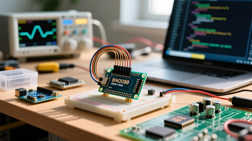
Historically, executing these floating-point matrix operations overwhelmed 8-bit AVR microcontrollers. However, by offloading the sensor fusion to a dedicated coprocessor, you can build a highly accurate INS using modern 32-bit boards. This guide details the configuration of an inertial navigation system Arduino setup utilizing the Hillcrest Labs SH-2 sensor hub found on the Adafruit BNO085/BNO086 breakouts, paired with an Arduino Uno R4 Minima.
Hardware Selection: IMU Comparison for Arduino INS
Selecting the right Inertial Measurement Unit (IMU) dictates your firmware complexity. While raw IMUs require you to write your own sensor fusion algorithms, system-in-package (SiP) IMUs handle this internally. Below is a comparison of popular 9-DOF sensors for INS applications.
| IMU Model | Architecture | Sensor Fusion Engine | Arduino INS Suitability | Approx. Cost (2026) |
|---|---|---|---|---|
| BNO055 | SiP (Bosch) | BSX3 (Legacy) | Good, but suffers from long-term yaw drift and I2C lockups. | $35.00 |
| BNO085 / BNO086 | SiP (Hillcrest/CEVA) | SH-2 (ARM Cortex-M0+) | Excellent. Hardware-accelerated quaternions, FRS calibration storage. | $42.00 |
| ICM-20948 | Raw + DMP (TDK InvenSense) | DMP (Digital Motion Processor) | Complex. DMP firmware loading is fragile; requires heavy I2C traffic. | $28.00 |
For a reliable inertial navigation system Arduino build, the BNO086 is the superior choice. Its internal SH-2 engine outputs stabilized quaternions at up to 400Hz, completely bypassing the need for the Arduino to perform intensive trigonometric calculations.
Wiring and Power Conditioning for the BNO086
A common failure mode in Arduino INS projects is I2C bus instability. The BNO086 can stretch the I2C clock while processing internal calibration routines, which crashes standard AVR Wire libraries. The Arduino Uno R4 Minima (featuring a 48MHz ARM Cortex-M4F) handles clock stretching natively, but physical wiring must still be optimized.
Critical I2C Configuration Steps
- Pull-up Resistors: The Adafruit breakout includes 10kΩ pull-ups. For a 400kHz I2C bus, replace these with 2.2kΩ resistors to ensure sharp signal rise times.
- Decoupling: Solder a 100nF ceramic capacitor and a 10µF tantalum capacitor directly across the VIN and GND pins on the breakout to suppress transient current spikes during gyroscope spin-up.
- Logic Levels: The BNO086 is strictly a 3.3V device. The Uno R4 Minima operates at 3.3V logic natively, eliminating the need for a logic level shifter. If using a 5V Nano, a bi-directional level shifter (like the BSS138) is mandatory to prevent frying the SH-2 hub.
Software Configuration: Initializing the SH-2 Sensor Hub
Unlike raw sensors, the BNO086 requires you to enable specific 'Sensor Reports' via the SH-2 Flash Record System (FRS). For an INS, you must configure the Game Rotation Vector (GRV) rather than the standard Rotation Vector (RV).
Expert Insight: The standard Rotation Vector fuses magnetometer data to establish absolute North. In indoor environments or near ferrous metals, magnetic distortion causes violent heading snaps. The Game Rotation Vector ignores the magnetometer, relying only on the accelerometer and gyroscope. This yields incredibly smooth relative heading tracking, which is ideal for dead-reckoning INS, though it will experience slow Z-axis (yaw) drift over time.
Configuring the FRS and Report Rates
Using the Adafruit BNO08x library, you must initialize the sensor and explicitly request the GRV report at a high frequency to minimize integration latency.
#include <Adafruit_BNO08x.h>
Adafruit_BNO08x bno08x(BNO08X_RESET);
sh2_SensorValue_t sensorValue;

void setup() {
  // Initialize I2C at 400kHz
  Wire.setClock(400000);
  bno08x.begin_I2C();

  // Enable Game Rotation Vector at 100Hz (10ms interval)
  // The SH-2 engine handles the Madgwick/Kalman filtering internally
  bno08x.enableReport(SH2_GAME_ROTATION_VECTOR, 10000);

  // Enable Linear Acceleration (Gravity removed) for position integration
  bno08x.enableReport(SH2_LINEAR_ACCELERATION, 10000);
}
Handling Drift and Sensor Fusion Edge Cases
Even with the SH-2 engine, an INS relying purely on GRV will accumulate yaw drift (typically 1° to 3° per minute). To build a viable inertial navigation system Arduino project, you must implement software mitigations and understand the physical edge cases.
1. Mitigating Z-Axis Yaw Drift
If your application involves a wheeled robot or vehicle, you can enforce a non-holonomic constraint. If you know the vehicle cannot move laterally (strafe), you can mathematically force the lateral velocity vector to zero in your Arduino sketch. This constraint feeds back into your extended Kalman filter (EKF), effectively using the vehicle's kinematics to correct the gyroscope's yaw drift without needing a magnetometer.
2. Managing Gyroscope Saturation
The BNO086 gyroscope has a maximum measurable range of ±2000 degrees per second (dps). If your project experiences sudden, violent impacts or high-speed rotations exceeding this threshold, the gyroscope will saturate and clip. The SH-2 fusion algorithm will lose its orientation baseline, resulting in a permanent offset until a full recalibration is triggered. Always mount the IMU near the center of mass (CoM) of your project to minimize rotational velocity during linear impacts.
Persistent Calibration via the Flash Record System (FRS)
One of the most powerful features of the SH-2 architecture is the Flash Record System. Standard IMUs lose their calibration data every time power is cycled, forcing the user to perform 'figure-eight' dances to recalibrate the magnetometer and gyroscope offsets. The BNO086 allows you to save these calibration vectors directly to its internal non-volatile memory.
Once your prototype is fully assembled in its final enclosure (which introduces hard-iron magnetic distortions), run a calibration routine. Once the SH-2 reports a calibration accuracy level of 3 (high), send the SH2_SAVE_DCD command via I2C. This burns the current bias and scale-factor matrices into the FRS. On subsequent power-ups, the BNO086 will load these environmental offsets instantly, providing navigation-grade accuracy from millisecond zero.
Integrating GPS for a Full INS (Loose Coupling)
An IMU-only system is technically an Inertial Measurement Unit. To become a true Inertial Navigation System, you must periodically correct the accumulated positional drift using an external absolute reference, typically GPS. This is known as loose coupling.
Connect a u-blox MAX-M10S GPS module to the Uno R4's secondary hardware serial port (Serial1). To properly fuse the GPS NMEA sentences with the BNO086's 100Hz IMU data, you must synchronize the timestamps.
- Parse the PPS Pin: Route the GPS Pulse-Per-Second (PPS) pin to an Arduino hardware interrupt. This provides a microsecond-accurate time anchor.
- Buffer IMU Data: Store the BNO086 linear acceleration and quaternion data in a circular buffer ring.
- Retroactive Correction: When the GPS calculates a new fix (which typically lags by 200ms to 500ms), use the PPS timestamp to retroactively apply the GPS position fix to the exact moment the satellite data was sampled, then re-integrate the buffered IMU data forward to the current time.
By combining the high-frequency relative tracking of the BNO086 with the low-frequency absolute truth of the GPS, your Arduino will maintain sub-meter positional accuracy even during brief GPS dropouts in tunnels or urban canyons.