
The Reality of Breadboard and Arduino Integration
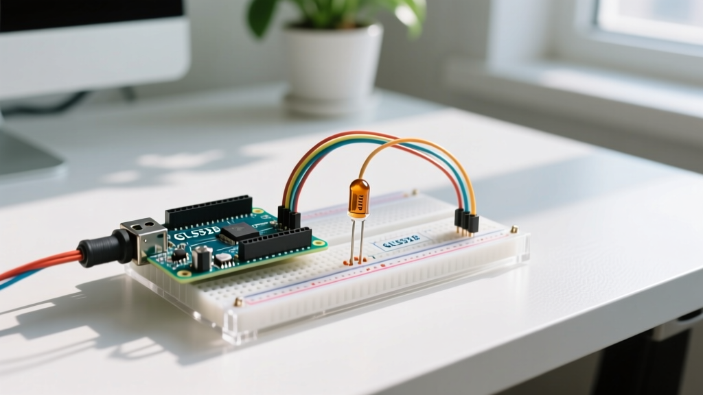
When prototyping embedded systems, the combination of a solderless breadboard and Arduino microcontrollers is the undisputed industry standard for rapid iteration. However, many makers encounter immediate physical and electrical roadblocks the moment they attempt to plug a development board directly into a prototyping matrix. Understanding the exact mechanical dimensions, logic-level tolerances, and power delivery constraints is critical to preventing damaged silicon and frustrating debugging sessions.
As of 2026, the transition from legacy 8-bit AVR boards to 32-bit ARM Cortex-M4 architectures (like the Uno R4 series) has fundamentally altered power budgets and logic thresholds. This comprehensive compatibility guide breaks down the physical fitment matrices, electrical limitations, and high-frequency signal integrity rules you need to know before wiring your next project.
Physical Fitment: The 'Straddle' Problem Explained
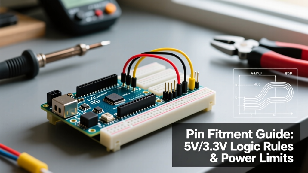
The most common point of confusion for beginners is why an Arduino Uno cannot simply be plugged across the center trench of a standard 830-point breadboard. The issue boils down to precise mechanical spacing.
- Arduino Uno Header Spacing: The digital I/O headers are spaced exactly 1.9 inches (48.26mm) apart. The power headers are spaced 2.0 inches (50.8mm) apart.
- Standard 830-Point Breadboard Trench: The center divider trench is typically 1.08 inches (27.5mm) wide.
Because the breadboard trench is significantly narrower than the Arduino header spacing, the pins cannot straddle the gap. If you attempt to force the board onto one side of the trench, the PCB will cover the tie-points, leaving you with no room to insert jumper wires. Furthermore, the power and digital headers on the Uno are not perfectly symmetrical in their Y-axis offset, meaning even if the trench were wide enough, the pins would misalign with the standard 0.1-inch (2.54mm) grid.
Board-to-Breadboard Compatibility Matrix
| Microcontroller Board | Header Spacing | Straddles 830-Point Trench? | Recommended Prototyping Method |
|---|---|---|---|
| Arduino Uno R4 Minima | 1.9" (Digital) | No | Use male-to-male jumpers or a Proto Shield |
| Arduino Nano Every | 0.9" (22.86mm) | Yes (Perfect Fit) | Direct insertion across center trench |
| Arduino Mega 2560 | Variable (Wing design) | No | Sensor shields or terminal block breakouts |
| Generic ESP32 DevKit V1 | 0.9" to 1.0" | Sometimes (Width dependent) | Use two adjacent half-size breadboards |
| Arduino Nano 33 IoT | 0.9" (22.86mm) | Yes (Perfect Fit) | Direct insertion across center trench |
Pro-Tip for Nano Users: While the Arduino Nano and Nano 33 IoT fit perfectly across the trench of an 830-point breadboard, they often block the top row of tie-points. To maximize workspace, plug the Nano in starting from row 2 or 3, leaving row 1 open for power rail jumping.
Electrical Compatibility: 5V vs. 3.3V Logic Levels
Physical fitment is only half the battle; electrical compatibility is where permanent hardware damage occurs. Modern maker ecosystems are heavily divided between 5V logic (legacy AVR and standard Uno/Mega boards) and 3.3V logic (ESP32, Raspberry Pi Pico, and Arduino Nano 33 series).
The Danger of 5V Tolerant Misconceptions
Many off-brand sensors and I2C modules sold on marketplace sites claim to be '5V tolerant' simply because they have a 3.3V voltage regulator onboard. However, SparkFun's logic level tutorials explicitly warn that a voltage regulator only protects the power domain, not the data pins. Feeding a 5V I2C SDA/SCL signal from an Arduino Uno R3 directly into a 3.3V ESP32 or a BME280 sensor will degrade the silicon gate oxide over time, eventually leading to latch-up and permanent failure.
Implementing Logic Level Translation
When mixing a 5V Arduino with 3.3V peripherals on a breadboard, you must use a bidirectional logic level shifter.
- MOSFET-Based Shifters (BSS138): Ideal for I2C buses. They are cheap (usually under $2.00 for a 4-channel breakout) and rely on the bus pull-up resistors to function. They are limited to roughly 400kHz I2C speeds.
- TI TXB0108 Translators: Better for high-speed SPI or UART. These auto-direction-sensing chips can handle megahertz-range clock speeds but struggle with heavy capacitive loads or I2C pull-ups. Expect to pay around $4.50 for a reputable breakout board.
Power Delivery and Thermal Throttling Constraints
A standard breadboard power rail is only as good as the source feeding it and the contact resistance of the metal clips inside the plastic housing. Understanding the exact current limits of your Arduino board is vital when powering breadboard peripherals like LED matrices, servo motors, or Wi-Fi radios.
Legacy Linear Regulators vs. Modern Buck Converters
If you are still using an older Arduino Uno R3, the board relies on an NCP1117ST50T3G linear regulator to drop voltage from the DC barrel jack to the 5V pin. If you supply 12V to the barrel jack and attempt to draw 300mA from the 5V breadboard rail, the regulator must dissipate (12V - 5V) * 0.3A = 2.1 Watts of heat. Without active cooling, the NCP1117 will hit its thermal shutdown threshold at roughly 150°C and abruptly cut power to your breadboard.
Conversely, the Arduino Uno R4 Minima utilizes a highly efficient DC-DC buck converter. This allows the R4 to safely deliver up to 1.5A to the breadboard's 5V rail when powered via the VIN pin, completely eliminating the thermal throttling issues of the R3 era. This makes the R4 vastly superior for breadboard projects involving high-current components like NeoPixel strips or MG996R servos.
Breadboard Contact Resistance and Voltage Drop
Do not assume your breadboard power rails are perfect conductors. Standard solderless breadboard clips exhibit a contact resistance of roughly 50 to 100 milliohms per connection point. If you daisy-chain power across 30 tie-points to reach the far end of an 830-point board, and your circuit draws 1A, you will experience a measurable voltage drop. For sensitive analog sensors or high-resolution ADCs, this ground-bounce and VCC sag will introduce severe noise into your readings. Always run redundant power and ground jumper wires every 20-30 holes along long breadboard arrays.
Signal Integrity: Parasitic Capacitance on Breadboards
Solderless breadboards are notorious for high-frequency signal degradation. According to hardware design principles outlined by Adafruit's breadboarding guides, the metal spring clips inside a breadboard create a parasitic capacitance of approximately 2pF to 5pF per node. While negligible for a 1Hz blinking LED or a simple push-button read, this capacitance becomes a massive liability for high-speed digital buses.
Why I2C and SPI Fail on Large Breadboards
When you combine 5pF of parasitic capacitance per hole with the inductance of long, stranded jumper wires (roughly 1nH per millimeter of wire length), you inadvertently create a low-pass LC filter. This filter rounds off the sharp edges of your digital square waves.
- I2C Bus Failures: The rounded waveforms cause the receiver to miss the setup/hold times required for ACK/NACK bits, resulting in random I2C bus lockups or 'NACK' errors in your serial monitor.
- SPI Clock Desync: At SPI clock speeds above 2MHz, the signal degradation can cause the slave device to read a single clock pulse as two, shifting the entire data register by one bit and returning garbage data.
Best Practices for High-Speed Breadboard Wiring
To maintain signal integrity when routing high-speed buses on a solderless matrix, follow these strict layout rules:
- Use 22 AWG Solid-Core Wire: Avoid pre-cut, stranded jumper wires with thick plastic insulation for high-speed lines. Solid-core wire has lower inductance and sits tighter in the breadboard clips, reducing microphonic noise and intermittent contact issues.
- Keep Traces Under 10cm: Route your SPI CLK, MOSI, and MISO lines directly adjacent to each other and keep their total physical length under 10 centimeters.
- Strengthen Pull-Up Resistors: The standard 10kΩ pull-up resistors used on I2C lines are often too weak to overcome breadboard capacitance. Drop the pull-up resistor value to 4.7kΩ or even 2.2kΩ to provide more current to charge the parasitic capacitance, resulting in sharper rising edges on your SDA and SCL lines.
Troubleshooting Intermittent Breadboard Connections
Even with perfect code, a breadboard and Arduino setup can fail due to mechanical wear. The internal leaf-spring clips are typically made of nickel-plated beryllium copper. Over time, and especially if you have been inserting thick 18 AWG component leads or square header pins, these clips stretch and lose their spring tension.
The 'Wiggle Test' Diagnostic: If your Arduino sketch hangs randomly or an LCD display drops characters, gently press down on the jumper wires while the circuit is powered. If the system responds to physical pressure, you have a high-resistance contact. The only reliable fix is to discard the worn section of the breadboard. Attempting to bend the internal clips back into shape with a needle or tweezers rarely provides lasting contact pressure and usually results in oxidized, unreliable connections.
Summary: Building Reliable Prototypes
Successfully pairing a breadboard and Arduino requires respecting both mechanical limits and electrical physics. Choose the right board form factor (like the Nano) if direct trench-straddling is required, respect the 5V/3.3V logic boundaries with proper translation ICs, leverage the superior power delivery of modern boards like the Uno R4, and mitigate parasitic capacitance when working with high-speed data buses. By treating the breadboard not just as a convenient wiring block, but as an active electrical component with its own tolerances, you will drastically reduce prototype debugging time and build far more robust proof-of-concept models.