
The Core Challenge: Moving Beyond PWM Audio
Most beginners attempting to build an arduino audio amplifier start by wiring a speaker directly to a digital PWM pin via a basic NPN transistor. While this generates sound, the result is a harsh, distorted square wave entirely unsuitable for music or high-fidelity voice reproduction. True audio requires smooth analog waveforms. To achieve this in the Arduino ecosystem, you must transition from 8-bit digital PWM to a true analog signal chain using a Digital-to-Analog Converter (DAC) paired with a dedicated Class-D amplifier module.
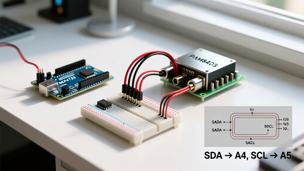
This configuration guide details how to interface an Arduino Uno R3 (or R4 Minima) with a 12-bit MCP4725 DAC and a PAM8403 Class-D amplifier. This combination yields clean, 2.5W stereo audio output, bypassing the inherent noise floor and quantization errors of native microcontroller PWM.
Hardware Selection Matrix: Choosing Your Amplifier
Selecting the right amplifier IC is critical for your signal chain. Below is a comparison of the most common amplifier modules used in maker projects as of 2026, highlighting why the PAM8403 is the optimal choice for analog DAC setups.
| Module | Architecture | Input Type | Max Output | Typical Price | Best Use Case |
|---|---|---|---|---|---|
| PAM8403 | Class-D | Analog (Single/Diff) | 3W + 3W (at 5V) | $1.50 - $3.00 | DAC-driven analog audio, portable speakers |
| MAX98357A | Class-D | I2S (Digital) | 3.2W (at 5V) | $5.00 - $7.50 | ESP32 I2S direct digital audio |
| LM386 | Class-AB | Analog | 1.25W (at 9V) | $1.00 - $2.00 | Legacy low-fidelity voice, simple alarms |
While the MAX98357A is superior for ESP32 I2S configurations, the PAM8403 remains the undisputed king for standard AVR-based Arduino boards utilizing external analog DACs due to its low cost, high efficiency, and 5V compatibility.
Circuit Configuration: DAC to Amplifier Signal Chain
Building a stable arduino audio amplifier circuit requires careful attention to signal coupling and power decoupling. We will use the Adafruit MCP4725 Breakout (or an equivalent generic clone) to generate the analog signal.
Step 1: I2C DAC (MCP4725) Wiring
The MCP4725 communicates via I2C. According to the official Arduino I2C documentation, the standard ATmega328P I2C pins are A4 (SDA) and A5 (SCL).
- VCC: Connect to Arduino 5V. (The MCP4725 will output a 0-5V analog range when powered at 5V).
- GND: Connect to Arduino GND.
- SCL: Connect to A5.
- SDA: Connect to A4.
- Pull-up Resistors: Most breakout boards include 10kΩ I2C pull-ups. If using a bare IC, you must add 4.7kΩ pull-up resistors from SDA and SCL to VCC.
Step 2: PAM8403 Class-D Amplifier Integration
The PAM8403 datasheet specifies that the IC utilizes differential inputs. When feeding a single-ended signal from the MCP4725, you must AC-couple the signal to prevent the DAC's DC bias from causing massive current draw and thermal shutdown in the amplifier.
- Connect the MCP4725 OUT pin to a 10µF electrolytic capacitor (positive leg to OUT).
- Connect the negative leg of the capacitor to the PAM8403 Left IN+ (or Right IN+).
- Add a 10kΩ pulldown resistor from the PAM8403 IN+ pin to GND. This establishes the correct DC operating point for the amplifier's internal comparator.
- Tie the PAM8403 IN- pin directly to GND.
- Connect VCC to 5V and GND to the common ground.
Expert Power Decoupling Warning: Class-D amplifiers draw high-frequency current spikes. If you do not place a 100µF electrolytic capacitor and a 100nF ceramic capacitor in parallel directly across the PAM8403 VCC and GND pins, you will experience severe "motorboating" (low-frequency oscillation) and audio dropout when bass notes hit.
Firmware Configuration: Timer Interrupts and Lookup Tables
To generate audio, we cannot use the standard analogWrite() or delay() functions, as they are blocking and lack the precise timing required for audio sample rates. We will configure Hardware Timer1 to trigger an interrupt at a 22,050 Hz sample rate (standard lo-fi audio rate), pushing values from a sine wave lookup table to the DAC via I2C.
#include <Wire.h>
#include <Adafruit_MCP4725.h>

Adafruit_MCP4725 dac;

// 22kHz Sine Wave Lookup Table (Pre-calculated 12-bit values)
const uint16_t sineTable[64] = {
  2048, 2249, 2447, 2642, 2831, 3013, 3185, 3346,
  3495, 3630, 3750, 3853, 3939, 4007, 4056, 4085,
  4095, 4085, 4056, 4007, 3939, 3853, 3750, 3630,
  3495, 3346, 3185, 3013, 2831, 2642, 2447, 2249,
  2048, 1847, 1649, 1454, 1265, 1083, 911, 750,
  601, 466, 346, 243, 157, 89, 40, 11,
  0, 11, 40, 89, 157, 243, 346, 466,
  601, 750, 911, 1083, 1265, 1454, 1649, 1847
};

volatile uint8_t sampleIndex = 0;

void setup() {
  Wire.begin();
  Wire.setClock(400000); // 400kHz Fast I2C
  dac.begin(0x60); // Default MCP4725 I2C address

  // Configure Timer1 for 22050 Hz interrupt
  noInterrupts();
  TCCR1A = 0;
  TCCR1B = 0;
  TCNT1 = 0;
  // 16MHz / 1 (prescaler) / 22050Hz = 725.6
  OCR1A = 725;
  TCCR1B |= (1 << WGM12); // CTC mode
  TCCR1B |= (1 << CS10);  // No prescaler
  TIMSK1 |= (1 << OCIE1A); // Enable timer compare interrupt
  interrupts();
}

ISR(TIMER1_COMPA_vect) {
  // Write 12-bit value to DAC
  dac.setVoltage(sineTable[sampleIndex], false);
  sampleIndex++;
  if (sampleIndex >= 64) sampleIndex = 0;
}

void loop() {
  // Main loop remains free for UI/button inputs
}
Optimizing I2C Bus Speed
Standard I2C operates at 100kHz, which is too slow to push 12-bit data at 22,050 samples per second. By invoking Wire.setClock(400000);, we enable Fast Mode I2C. This reduces the transmission time per sample to roughly 35 microseconds, leaving ample CPU cycles for the rest of your sketch.
Advanced Troubleshooting: Eliminating Hiss and Motorboating
Even with perfect code, analog audio circuits are highly susceptible to environmental noise. Use this diagnostic matrix to resolve common arduino audio amplifier issues:
- Issue: Persistent 50/60Hz Hum.
Cause: Ground loop or shared power rails with high-current components (like motors or LED strips).
Fix: Implement a star-ground topology. Connect the DAC GND, Amplifier GND, and Arduino GND at a single physical point, rather than daisy-chaining them on a breadboard. - Issue: High-Frequency Hiss (White Noise).
Cause: Breadboard parasitic capacitance on the I2C lines corrupting the least significant bits of the DAC, or thermal noise from the 10kΩ pulldown resistor.
Fix: Move the circuit to a soldered perfboard. Keep the I2C traces under 5cm. If hiss persists, lower the pulldown resistor to 4.7kΩ to reduce the thermal noise floor, but ensure the DAC can source the extra current. - Issue: Audio Clipping / Distortion on Bass.
Cause: Power supply voltage sag. The PAM8403 can draw up to 1.5A instantaneously on heavy bass transients. Standard USB ports limit current to 500mA.
Fix: Power the PAM8403 VCC directly from a dedicated 5V 2A buck converter or wall adapter, bypassing the Arduino's onboard 5V regulator entirely. - Issue: I2C Bus Lockups.
Cause: Missing pull-up resistors or bus capacitance exceeding 400pF.
Fix: Verify the breakout board has onboard pull-ups. If using long wires, add active I2C bus extenders (like the PCA9600) or switch to an SPI-based DAC like the MCP4921.
References and Further Reading
For deeper technical specifications and alternative configurations, consult the following authoritative resources:
- Adafruit MCP4725 12-Bit I2C DAC Breakout Board - Hardware overview and library documentation.
- Diodes Incorporated PAM8403 Datasheet - Official electrical characteristics, thermal shutdown thresholds, and AC-coupling schematics.
- Arduino Official I2C Communication Guide - Bus topology, pull-up requirements, and Wire library limitations.