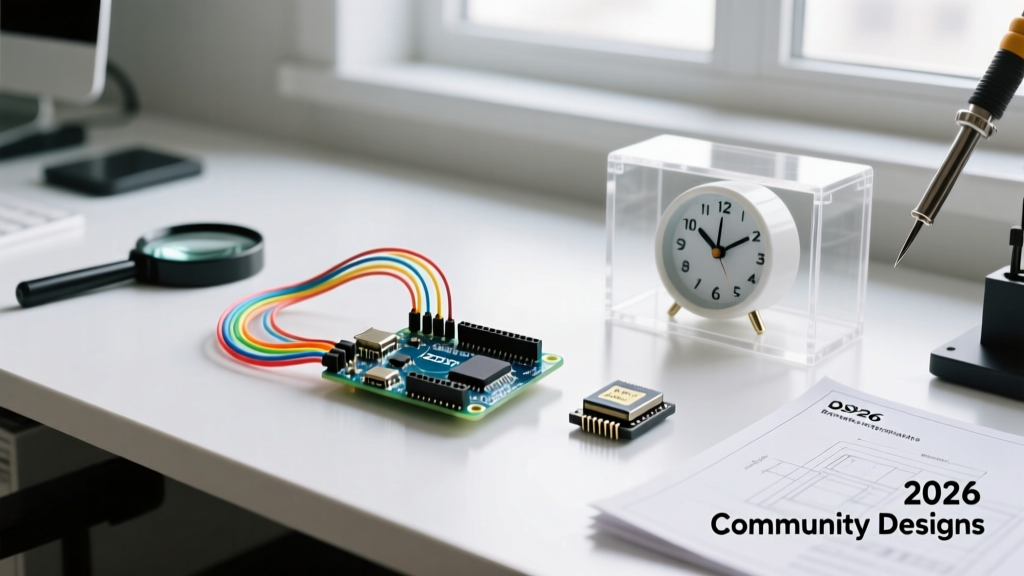

The Evolution of the Arduino Alarm Clock in 2026
Building an alarm clock with Arduino remains a definitive rite of passage for makers, but the community standard has shifted dramatically. Gone are the days of relying on the millis() function and a screeching passive piezo buzzer. In 2026, the open-source hardware community favors precision timekeeping, multi-format audio wake-ups, and ultra-low-power sleep states. Whether you are designing a minimalist bedside display or a complex sunrise-simulating wake-up light, leveraging community-tested architectures prevents weeks of debugging.
This roundup synthesizes the most reliable, forum-vetted blueprints for building an alarm clock with Arduino, focusing on exact component models, real-world failure modes, and the specific wiring edge cases that often derail beginner projects.
The Timekeeping Core: DS3231SN vs. Legacy RTCs
The foundation of any reliable alarm clock with Arduino is the Real-Time Clock (RTC) module. While the DS1307 was the default choice a decade ago, the community has universally migrated to the DS3231SN for its integrated temperature-compensated crystal oscillator (TCXO).
| Feature | DS1307 | DS3231SN (Community Standard) | PCF8523 |
|---|---|---|---|
| Accuracy | ±5 mins/month (Temp dependent) | ±2ppm (approx. 1 min/year) | ±3ppm |
| Operating Voltage | 4.5V - 5.5V | 2.3V - 5.5V | 1.6V - 5.5V |
| Alarm Pins | None (Requires polling) | 2 (INT/SQW) | 1 (INT1) |
| 2026 Avg. Price | $1.50 - $2.00 | $3.00 - $4.50 | $4.00 - $5.50 |
Critical Edge Case: The CR2032 Charging Flaw
When sourcing DS3231 modules from budget marketplaces, you will frequently encounter boards equipped with a rechargeable LIR2032 battery and a surface-mount charging circuit. Do not use a standard non-rechargeable CR2032 on these unmodified boards. The charging circuit will attempt to charge the primary lithium cell, leading to overheating and potential rupture. The community consensus fix is to locate the diode or resistor labeled D1 or R1 near the battery holder and remove it with a soldering iron, effectively disabling the charging path. For a comprehensive look at the TCXO architecture, refer to the official Analog Devices DS3231 datasheet.
Audio & Display Configurations (Forum Favorites)
The way your alarm clock interacts with you dictates its component stack. Below are the top three community-approved configurations for an alarm clock with Arduino in 2026.
1. The Minimalist: TM1637 & Passive Buzzer
- Display: TM1637 4-digit 7-segment (0.56 inch). Cost: ~$1.50.
- Audio: 5V Active Piezo Buzzer.
- Library:
TM1637Displayby Avishay Orpaz. - Expert Insight: The TM1637 uses a custom I2C-like protocol but lacks standard addressing. It requires exactly two digital pins (CLK and DIO). To prevent the colon from flickering during alarm states, use the
setBrightness(0x08, true)method to enable the colon toggle independently of the digit refresh rate.
2. The Audiophile: OLED & DFPlayer Mini
- Display: SSD1306 128x64 I2C OLED. Cost: ~$4.50.
- Audio: DFPlayer Mini MP3 Module + 3W 4-Ohm Speaker. Cost: ~$3.50.
- Library:
DFRobotDFPlayerMini&Adafruit_SSD1306. - Expert Insight: The DFPlayer Mini operates at 3.3V logic. If you are using a 5V Arduino Nano or Uno, you must place a 1kΩ resistor in series with the Arduino's TX pin (connected to the DFPlayer's RX) to prevent logic-level damage over time. Furthermore, the module requires a 1.5 to 2-second delay in the
setup()function after power-on before it can accept serial commands. Omitting this delay is the #1 reason forum users report "dead on arrival" audio modules.
3. The Sleep-Saver: E-Ink & Ultra-Low Power
- Display: Good Display 2.9" E-Ink (GDEH029A1). Cost: ~$11.00.
- Audio: Low-power MEMS oscillator + Class-D PAM8403 Amp.
- Expert Insight: E-ink displays only draw current during a screen refresh (approx. 20mA for 1.5 seconds). By utilizing the ATmega328P's
power_downsleep mode and waking via the DS3231's INT pin, the entire clock can run for months on a single 18650 Li-Ion cell.
Power Management: Defeating the Vampire Drain
A common complaint when building a portable alarm clock with Arduino is the rapid depletion of batteries. A standard Arduino Nano clone utilizing the AMS1117-5.0 voltage regulator and the CH340G USB-serial chip draws an idle current of 15mA to 22mA. This is unacceptable for battery-operated bedside clocks.
Community Hardware Mod: To drop the quiescent current to under 2mA, makers physically desolder the onboard power LED and replace the AMS1117 with an MCP1700-3302E (3.3V LDO), which has a quiescent current of just 1.6µA. Pair this with a 3.3V Pro Mini clone for optimal efficiency.
For true deep sleep, utilize the RTClib library to configure the DS3231's Alarm 1. Wire the RTC's SQW/INT pin to the Arduino's INT0 (Pin 2 on an Uno/Nano). Use the LowPower.powerDown(SLEEP_FOREVER, ADC_OFF, BOD_OFF) function. When the alarm time is reached, the RTC pulls the INT pin LOW, triggering the hardware interrupt and waking the MCU instantly.
User Input: Rotary Encoders vs. Tactile Buttons
Setting the time and alarm on an Arduino clock using standard tactile buttons often leads to frustrating "double-counting" due to mechanical bounce. The 2026 community standard is the KY-040 Rotary Encoder with a built-in pushbutton.
- Wiring: Connect CLK to Pin 3 (INT1), DT to Pin 4, and SW to Pin 5.
- Software: Use the
Bounce2library for the pushbutton, and a hardware interrupt on the CLK pin to read the DT pin state. This guarantees zero missed steps, even on slower 8MHz ATmega328P setups. - Hardware Tip: Add 100nF ceramic capacitors between the CLK/SW pins and GND to filter out high-frequency EMI noise, which is especially prevalent if the clock is placed near switching power supplies or Wi-Fi routers.
2026 BOM Pricing & Sourcing Guide
Below is a realistic Bill of Materials (BOM) for building a high-end, audiophile-grade alarm clock with Arduino, based on early 2026 market pricing from major distributors and vetted community suppliers.
| Component | Model / Specification | Est. Cost (USD) |
|---|---|---|
| MCU Board | Arduino Pro Mini 3.3V (8MHz) | $4.50 |
| RTC Module | DS3231SN (with EEPROM) | $3.80 |
| Audio Decoder | DFPlayer Mini + 16GB MicroSD | $8.50 |
| Amplifier & Speaker | PAM8403 + 3W 4-Ohm Driver | $4.20 |
| Display | 1.3" I2C OLED (SH1106) | $5.10 |
| Input | KY-040 Rotary Encoder | $1.80 |
| Total Estimated BOM | Excluding enclosure and wiring | $27.90 |
Troubleshooting Common Forum Pitfalls
Even with the best components, building an alarm clock with Arduino presents unique integration challenges. Here are the most frequently documented issues on Hackaday and the official Arduino forums, along with their definitive fixes:
- I2C Bus Hanging on Boot: If the OLED and DS3231 are on the same I2C bus, and the user powers the Arduino via the RAW pin while the RTC is on battery backup, the SDA line can get stuck LOW. Fix: Add 4.7kΩ pull-up resistors to both SDA and SCL lines tied to the MCU's VCC, not the RTC's VCC.
- DFPlayer Mini "Busy" Pin False Positives: The BUSY pin on the MP3 module is active LOW, but it floats during initialization. Fix: Add a 10kΩ pull-up resistor to the BUSY pin and enforce a 500ms software debounce before checking its state in your
loop(). - OLED Screen Burn-in: Leaving static time digits on an I2C OLED for months will degrade the phosphors. Fix: Implement a "pixel shift" routine in your code that moves the entire display buffer by 1 pixel in a circular pattern every 60 seconds.
By adopting these community-refined architectures and respecting the electrical quirks of legacy and modern modules alike, your DIY alarm clock will transition from a weekend novelty to a reliable, daily-use appliance.