
The Hardware Reality: 3.3V Logic and Bus Capacitance
Integrating microcontrollers and sensors into a Single Board Computer (SBC) ecosystem is a cornerstone of advanced maker projects. When configuring I2C with Raspberry Pi, the first hurdle is understanding the hardware quirks of the Broadcom BCM2835 and BCM2711 SoCs. Unlike standard 5V Arduino microcontrollers, the Raspberry Pi operates strictly at 3.3V logic levels. Applying 5V to the Pi's GPIO pins will permanently damage the silicon.
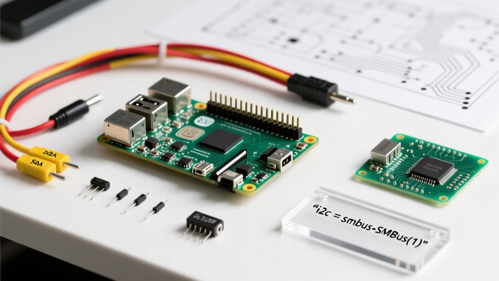
Furthermore, the Raspberry Pi's primary I2C bus (GPIO 2 / SDA and GPIO 3 / SCL) features internal 1.8kΩ pull-up resistors tied to the 3.3V rail. According to the NXP I2C-bus specification, the minimum pull-up resistance is dictated by the maximum sink current (typically 3mA). If you connect an external sensor module that already includes 4.7kΩ pull-up resistors, the parallel equivalent resistance drops to approximately 1.3kΩ. This results in a sink current of roughly 2.5mA, which is safe, but leaves very little margin for error if you add more devices to the bus.
Expert Warning: Never connect a 5V I2C device (like a standard 5V Arduino Uno acting as a slave, or a 5V LCD backpack) directly to the Pi's I2C pins. The SDA/SCL lines will be pulled up to 5V, back-feeding the Pi's 3.3V regulator and potentially destroying the GPIO pad ring.
Step-by-Step: Enabling the I2C Interface
Before writing any code, the hardware I2C peripheral must be enabled in the device tree. While older tutorials suggest editing /boot/config.txt manually, the safest method is using the official configuration tool.
- Open the terminal and type:
sudo raspi-config - Navigate to Interface Options > I2C and select Yes to enable the ARM I2C interface.
- Reboot the Pi:
sudo reboot - Install the diagnostic tools:
sudo apt update && sudo apt install i2c-tools
Once installed, scan the bus using i2cdetect -y 1. A properly wired BME280 sensor, for instance, will appear at address 0x76 or 0x77.
Wiring Strategy: Level Shifting and Bus Capacitance
When bridging the gap between 3.3V Pi logic and 5V MCU ecosystems, you must use a bidirectional level shifter. The I2C bus is open-drain, meaning devices only pull the line low; they never drive it high. Therefore, standard unidirectional logic level converters (like the 74HC595 or simple voltage dividers) will fail. You need MOSFET-based bidirectional shifters.
| Method | IC / Topology | Max Speed | Pros & Cons |
|---|---|---|---|
| BSS138 Module | N-channel MOSFET | 400 kHz | Cheap and ubiquitous. Can struggle with high bus capacitance (>200pF) due to gate charge times. |
| PCA9306 | Dedicated I2C Translator | 1 MHz | Optimized for I2C. Features an enable pin and handles capacitance beautifully. Best for professional prototyping. |
| Optocoupler (e.g., TCA9548A with isolation) | Galvanic Isolation | 100 kHz | Protects the Pi from high-voltage spikes in industrial motor-control MCU environments. Introduces propagation delay. |
Remember that the I2C bus has a strict maximum capacitance limit of 400pF. Long jumper wires and breadboards add parasitic capacitance. If your signals degrade, lower the bus speed to 100kHz or use shorter, shielded cables.
Python Implementation: Reading Sensors via smbus2
The legacy smbus library is largely unmaintained. For modern Python development on the Pi, the smbus2 library is the industry standard. It supports pure Python fallbacks and advanced features like I2C block reads.
Install it via pip: pip3 install smbus2.
Below is a robust implementation for reading the Chip ID from a BME280 sensor to verify communication before attempting complex data parsing.
import smbus2
import time

# Raspberry Pi I2C bus 1 (GPIO 2 and 3)
BUS = 1
BME280_ADDR = 0x76
CHIP_ID_REG = 0xD0

def verify_sensor():
    try:
        with smbus2.SMBus(BUS) as bus:
            # Read a single byte from the Chip ID register
            chip_id = bus.read_byte_data(BME280_ADDR, CHIP_ID_REG)
            if chip_id == 0x60:
                print(f'Success: BME280 detected with Chip ID: {hex(chip_id)}')
            elif chip_id == 0x58:
                print(f'Success: BMP280 detected with Chip ID: {hex(chip_id)}')
            else:
                print(f'Warning: Unknown device at address. ID: {hex(chip_id)}')
    except OSError as e:
        print(f'I2C Communication Failed: {e}')
        print('Check wiring, pull-up resistors, and level shifters.')

if __name__ == '__main__':
    verify_sensor()
Advanced Troubleshooting: The Clock Stretching Bug
If you are using your Raspberry Pi as an I2C Master to communicate with an Arduino configured as an I2C Slave, you will likely encounter the infamous Broadcom Clock Stretching bug. As documented in the Raspberry Pi hardware peripherals documentation, the hardware I2C controller on the BCM2835/BCM2711 does not properly support clock stretching.
Clock stretching occurs when a slave device (like an Arduino processing a heavy Wire.onRequest() callback) holds the SCL line LOW to pause the master until it is ready to send data. The Pi's hardware I2C peripheral fails to recognize this stretched state, times out, and throws an OSError: [Errno 121] Remote I/O error, permanently locking the bus until a reboot.
The Fix: Software I2C Overlay
To bypass the hardware limitation, you must force the Pi to use a bit-banged software I2C bus, which handles clock stretching flawlessly.
- Open your config file:
sudo nano /boot/firmware/config.txt(or/boot/config.txton older OS versions). - Add the following line to the bottom to map software I2C to GPIO 23 (SDA) and GPIO 24 (SCL):
dtoverlay=i2c-gpio,i2c_gpio_sda=23,i2c_gpio_scl=24 - Reboot the Pi.
After rebooting, running i2cdetect -y 3 (the software bus usually maps to bus 3) will show your devices. Update your Python code to use smbus2.SMBus(3) instead of bus 1. This single configuration change resolves 90% of the 'unexplained' I2C crashes when bridging Raspberry Pi and Arduino ecosystems.