
The Problem with Legacy Audio Workflows
When makers first attempt to play music from Arduino, the standard tutorial path inevitably leads to the tone() function and a piezo buzzer. While sufficient for simple 8-bit beeps, this approach generates harsh square waves, blocks the main execution loop, and completely fails to reproduce polyphonic audio or sampled music. As of 2026, the microcontroller ecosystem has matured significantly. With the widespread adoption of the RP2040 and ESP32-S3 alongside legacy AVR boards, relying on CPU-bound PWM for audio is an obsolete bottleneck.
To achieve high-fidelity audio playback without starving your main application loop, you must transition to a hardware-optimized workflow utilizing Digital-to-Analog Converters (DACs), Inter-IC Sound (I2S) protocols, and Direct Memory Access (DMA). This guide outlines a professional, non-blocking workflow to integrate pristine audio into your MCU projects.
Hardware Selection Matrix: Choosing the Right Audio Path
Before writing a single line of code, you must select the correct hardware interface. Your choice dictates the sample rate, CPU overhead, and overall audio fidelity. Below is a comparison of the most common methods used to play music from Arduino environments today.
| Method | Hardware IC / Setup | Resolution | Max Sample Rate | CPU Overhead | Est. Cost (2026) |
|---|---|---|---|---|---|
| PWM + RC Filter | ATmega328P Timer1 | 8-bit | ~16 kHz | High (Interrupt driven) | < $1.00 |
| I2C DAC | MCP4725 | 12-bit | ~12 kHz | Medium (I2C bus blocking) | $4.50 - $6.00 |
| I2S DAC (Line Out) | PCM5102A | 16/24-bit | 192 kHz | Near Zero (DMA driven) | $5.00 - $8.00 |
| I2S Amplifier | MAX98357A | 16-bit | 96 kHz | Near Zero (DMA driven) | $7.00 - $9.50 |
Workflow Recommendation: For any project requiring actual music playback (WAV files, synthesized polyphony, or MP3 decoding), bypass I2C and PWM entirely. The MAX98357A I2S amplifier is the current industry standard for makers. It handles the digital-to-analog conversion and amplification on a single chip, requiring only three digital pins (BCLK, LRC, DIN) from your microcontroller.
Phase 1: Audio Asset Preparation Pipeline
Microcontrollers lack the floating-point运算 units (FPUs) and massive RAM buffers required to decode heavily compressed formats like AAC or high-bitrate MP3s on the fly. The most optimized workflow relies on uncompressed Pulse-Code Modulation (PCM) WAV files.
Optimizing Sample Rates and Bit Depth
Do not use standard 44.1 kHz / 16-bit stereo CD-quality audio unless you are using an ESP32-S3 with PSRAM. For standard RP2040 or ATmega2560 workflows, downsample your audio to 22050 Hz, 16-bit, Mono. This cuts the memory and SD card read bandwidth requirements by 75% while retaining excellent fidelity for voice and most instruments.
The FFmpeg Conversion Command
Stop using basic audio editors that inject metadata headers which confuse MCU SD card libraries. Use FFmpeg via the command line to strip metadata and enforce strict PCM formatting:
ffmpeg -i original_track.mp3 -ar 22050 -ac 1 -sample_fmt s16 -f wav -bitexact optimized_audio.wav-ar 22050: Sets the sample rate to 22.05 kHz.-ac 1: Forces mono output.-sample_fmt s16: Ensures 16-bit signed integer format (required by most I2S DMA buffers).-bitexact: Strips non-standard metadata chunks that cause SD libraries to misread the WAV header.
Phase 2: SD Card & SPI Bus Optimization
Audio dropouts and stuttering are rarely caused by the DAC; they are almost always caused by SD card read latency. The SD Association standards dictate complex internal wear-leveling and garbage collection processes that can cause momentary SPI bus locks.
Formatting for Low Latency
Format your MicroSD card to FAT32 with a 32 KB Allocation Unit Size (Cluster Size). Standard formatters often default to 4 KB clusters, which forces the MCU to perform four times as many file-system table lookups per second, drastically increasing the chance of buffer underruns.
Tuning the SPI Clock
The default Arduino SD.h library initializes the SPI bus at a conservative 4 MHz. If you are using an RP2040 or ESP32, you must override this to feed the I2S DMA buffer fast enough. Initialize your SD card with a higher clock divisor:
// Example for RP2040 / ESP32 high-speed SPI initialization
SD.begin(SD_CS_PIN, SPI, 20000000); // Force 20 MHz SPI clock
Note: Ensure your physical wiring is short (under 5 inches) and uses proper grounding when pushing SPI past 10 MHz to avoid signal reflection and CRC errors.
Phase 3: Non-Blocking Code Architecture via DMA
The core of an optimized audio workflow is decoupling the audio stream from the loop() function. In 2026, the most robust way to achieve this in the Arduino ecosystem is by leveraging Phil Schatzmann’s arduino-audio-tools library, which abstracts the complex I2S and DMA register configurations across dozens of MCU architectures.
Understanding Double-Buffering
The Double-Buffering Concept:
Instead of reading a byte and pushing it to the DAC (which blocks the CPU), DMA uses two memory buffers (e.g., 1024 bytes each). While the DAC plays Buffer A via hardware interrupts, the CPU silently reads the next 1024 bytes from the SD card into Buffer B. When Buffer A finishes, the hardware instantly swaps to Buffer B, and the CPU refills Buffer A. This guarantees zero-dropout audio while leaving 90% of your CPU cycles free for LED animations, motor control, or sensor polling.
Implementation Workflow
When configuring your I2S stream, always match your buffer size to your SD card's read latency. A buffer that is too small will cause 'popping' (buffer underrun). A buffer that is too large will consume precious SRAM.
- ATmega328P (2KB SRAM): Max 256-byte buffers. (I2S not natively supported, requires external SPI DAC).
- RP2040 (264KB SRAM): 1024 to 2048-byte buffers. Ideal for I2S DMA.
- ESP32-S3 (512KB+ SRAM): 2048 to 4096-byte buffers. Allows for massive safety margins against SD card latency spikes.
Troubleshooting Common Audio Artifacts
Even with an optimized workflow, hardware realities can introduce audio artifacts. Use this diagnostic checklist to identify and resolve common failure modes:
1. Rhythmic Clicking or Popping
Cause: Buffer Underrun. The CPU is not feeding the DMA buffer fast enough.
Fix: Increase the I2S buffer size in your code. If already at 2048 bytes, check for blocking code in your main loop() (e.g., delay(), unoptimized Wire.requestFrom() I2C sensor reads, or heavy Serial.print() debugging). Move sensor reads to a secondary core if using an RP2040 or ESP32.
2. High-Pitched Whine or Hiss
Cause: I2S Clock Jitter or Ground Loops.
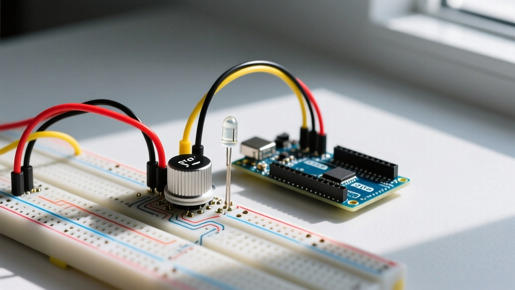
Fix: I2S relies on precise Bit Clock (BCLK) and Left-Right Clock (LRCLK) timing. If using jumper wires on a breadboard, parasitic capacitance will degrade the square wave edges, causing the DAC to misread bits. Solder the BCLK, LRCLK, and DIN lines directly, or use a ribbon cable with interleaved ground wires. Ensure the MCU and the MAX98357A share a common, star-routed ground plane.
3. Audio Plays at Half-Speed / Pitch Shifted
Cause: Sample Rate Mismatch or Stereo/Mono Confusion.
Fix: If your WAV file is 16-bit Stereo (32 bits per sample frame) but your I2S configuration is set to Mono (16 bits per frame), the DAC will interpret the left and right channels as sequential mono samples, halving the playback speed and dropping the pitch by an octave. Re-run the FFmpeg command with -ac 1 to force true mono at the file level.
Conclusion
Learning how to play music from Arduino with professional fidelity requires abandoning legacy tone() functions and embracing hardware-level protocols. By selecting an I2S DAC like the MAX98357A, rigorously pre-processing your WAV assets via FFmpeg, optimizing your SD card SPI bus, and utilizing DMA double-buffering, you transform a simple microcontroller into a robust, non-blocking audio engine. This workflow ensures your audio remains pristine while your main application logic runs entirely uninterrupted.