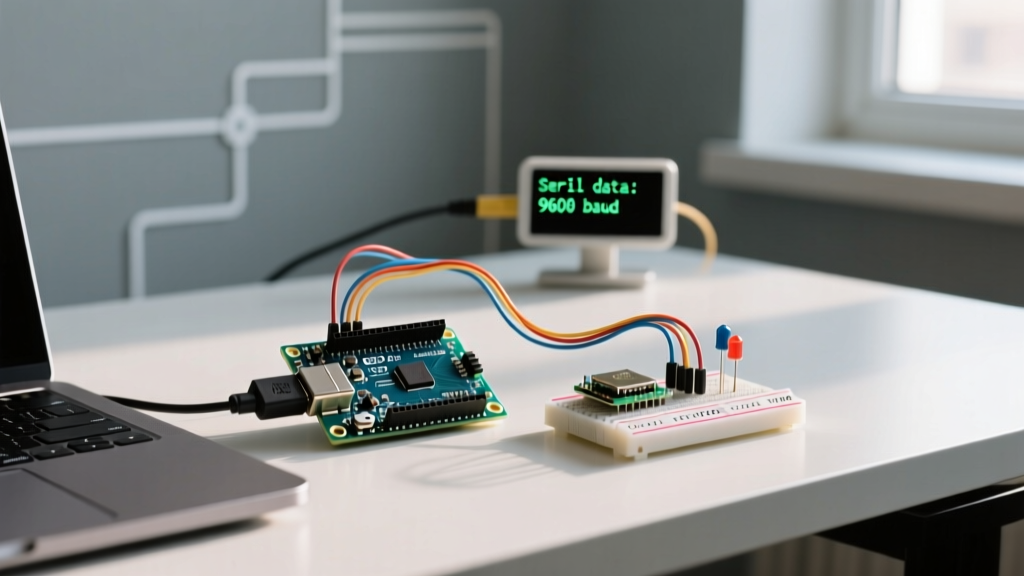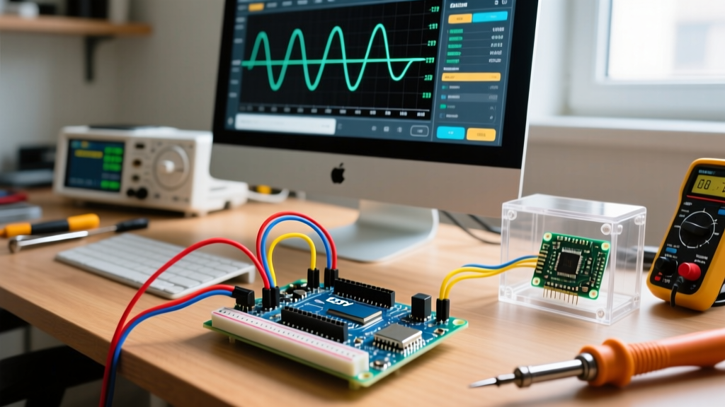

The Case for an Arduino Oscilloscope PC Workflow
In the modern electronics lab of 2026, a benchtop digital storage oscilloscope (DSO) like the Rigol DS1054Z or Siglent SDS1202X-E remains the gold standard for signal analysis, typically costing between $350 and $450. However, for rapid prototyping, low-frequency PWM debugging, and educational environments, waiting for a benchtop unit to boot and configure is a workflow bottleneck. Building an arduino oscilloscope pc interface bridges this gap, transforming a $4 microcontroller into a functional, PC-tethered diagnostic tool.
This guide focuses strictly on workflow optimization: bypassing software abstraction layers, eliminating serial bottlenecks, and integrating the data stream directly into your PC-based debugging environment. By treating the microcontroller not as a standalone computer, but as a raw analog-to-digital front-end, you can achieve sample rates and visualization speeds that rival entry-level dedicated USB scopes.
Hardware Boundaries: ATmega328P vs. RP2040 vs. Benchtop DSO
Before writing a single line of firmware, you must understand the physical limitations of your chosen silicon. The classic ATmega328P (found on the Uno and Nano) is heavily constrained by its 10-bit SAR ADC and lack of native USB. Modern workflows increasingly favor the RP2040 (Raspberry Pi Pico) or ATmega32U4 (Leonardo/Micro) for PC-tethered data acquisition.
| Platform | ADC Resolution | Max Practical Sample Rate | PC Interface Bottleneck | Approx. Cost (2026) |
|---|---|---|---|---|
| Arduino Nano (ATmega328P) | 10-bit | ~76 kHz (Register Tweaked) | UART-to-USB Bridge (115k baud) | $4.00 - $6.00 |
| Arduino Micro (ATmega32U4) | 10-bit | ~76 kHz | Native USB (Up to 1M+ baud) | $8.00 - $12.00 |
| RP2040 (Pico / Clones) | 12-bit | ~500 kHz (Dual Core/PIO) | Native USB Bulk Transfer | $3.00 - $5.00 |
| Entry-Level Benchtop DSO | 8-bit to 12-bit | 1 GSa/s | None (Standalone) | $350.00+ |
Optimizing the Acquisition Pipeline
The default analogRead() function in the Arduino IDE is designed for safety and ease of use, not speed. It configures the ADC multiplexer, waits for the conversion to complete, and returns a 16-bit integer. On a 16MHz ATmega328P, this takes approximately 104 microseconds, yielding a dismal 9.6 kHz sample rate—barely enough to capture a 4kHz audio signal without severe aliasing.
Bypassing analogRead() for Direct Port Manipulation
To optimize your arduino oscilloscope pc workflow, you must interact directly with the ADC hardware registers. According to the Arduino Port Manipulation documentation, bypassing the Arduino abstraction layer reduces overhead drastically.
The ADC clock is derived from the system clock via a prescaler. By default, the prescaler is set to 128, resulting in a 125 kHz ADC clock. A standard conversion takes 13 ADC cycles, resulting in the aforementioned 9.6 kHz sample rate. By modifying the ADCSRA (ADC Control and Status Register A) and dropping the prescaler to 16, the ADC clock becomes 1 MHz. This pushes the sample rate to roughly 76 kHz. While the Microchip ATmega328P datasheet notes that maximum 10-bit resolution requires an ADC clock between 50 kHz and 200 kHz, pushing to 1 MHz yields roughly 8 to 9 effective bits of resolution—a perfectly acceptable trade-off for time-domain visualization of digital and PWM signals.
Workflow Pro-Tip: When writing the acquisition loop, store the sampled data in a pre-allocated SRAM buffer (e.g.,uint8_t buffer[512];) and stream it in chunks. CallingSerial.write()inside the interrupt service routine (ISR) or tight polling loop will cause massive timing jitter due to UART buffer blocking.
Overcoming the UART Bottleneck
The most common failure point in an arduino oscilloscope pc setup is the data transfer bottleneck. A standard hardware UART running at 115,200 baud can transfer roughly 11,520 bytes per second. If your 10-bit ADC outputs 2 bytes per sample, your maximum throughput over the serial monitor is capped at 5,760 samples per second, entirely negating your 76 kHz hardware sampling speed.
The Native USB Solution
To resolve this, workflow optimization dictates abandoning the ATmega328P for PC-tethered scopes in favor of Native USB architectures. Boards utilizing the ATmega32U4 or the RP2040 communicate directly over USB CDC (Communications Device Class) or raw HID/Bulk endpoints. As detailed in the PJRC Teensy USB Serial optimization guide, native USB architectures can sustain baud rates of 1,000,000 to 2,000,000+ without hardware UART limits, limited only by the PC's USB polling rate and the host application's read buffer. If you must use an Uno/Nano, implement a circular buffer in SRAM to capture high-speed bursts, then pause acquisition to slowly dump the buffer to the PC.
Signal Conditioning: Protecting the 5V Rails
A critical edge case that destroys microcontrollers in oscilloscope workflows is voltage transients. The ATmega328P and RP2040 ADC pins are strictly limited to VCC (5V or 3.3V). Probing a 12V motor driver PWM or an RS-232 line will instantly fry the silicon.
- Resistive Voltage Dividers: For DC and low-frequency AC, use a precision resistor network. A 10kΩ and 2.2kΩ divider will safely scale a 24V signal down to ~4.3V. Refer to the SparkFun Voltage Divider Tutorial for exact impedance matching calculations to ensure the ADC's internal sample-and-hold capacitor charges fully within the acquisition window.
- Zener Clamping: Place a 4.7V or 3.3V Zener diode (depending on your MCU logic level) from the analog input to ground. This acts as a fast-acting transient voltage suppressor (TVS).
- Op-Amp Buffering: For high-impedance signals, the ADC's internal sampling switch will cause voltage droop. Buffer the signal using a rail-to-rail op-amp (like the MCP6001 or LM358) configured as a unity-gain follower before feeding it to the MCU.
PC-Side Software & Data Visualization
The PC interface is where the raw byte stream becomes actionable data. While the built-in Arduino IDE Serial Plotter is sufficient for quick checks, it lacks triggering, scaling, and export capabilities required for serious workflow optimization.
- Processing IDE / Custom Java GUIs: Writing a custom GUI in Processing allows you to implement software-based edge triggering. You can program the PC to freeze the buffer update when a sample crosses a specific threshold (e.g., >2.5V), mimicking the 'Single' trigger mode of a benchtop DSO.
- Python with PySerial and Matplotlib: For automated testing workflows, a Python script reading the COM port at 1M baud and piping data into a rolling Matplotlib array allows for real-time FFT (Fast Fourier Transform) analysis using the
numpy.fftlibrary, turning your arduino oscilloscope pc setup into a basic spectrum analyzer. - Dedicated Third-Party Apps: Open-source projects like SerialPlot or Girino provide pre-built oscilloscope UIs with adjustable timebases, multi-channel overlay, and CSV export functionality, saving hours of custom GUI coding.
Troubleshooting Common Failure Modes
Even with optimized code, physics and electrical noise will interfere with your readings. Here is how to diagnose the most frequent issues:
1. Severe Aliasing and Ghost Frequencies
Symptom: A 10kHz square wave appears on the PC screen as a slow-moving, chaotic sine wave. Cause: You are violating the Nyquist-Shannon sampling theorem. Your effective sample rate (after UART bottlenecks) is lower than twice the signal frequency. Fix: Implement hardware analog low-pass filtering (an RC filter with a cutoff frequency at half your sample rate) before the ADC pin to eliminate high-frequency noise folding back into your baseband.
2. USB Ground Loops
Symptom: 50Hz/60Hz mains hum is superimposed on your DC measurements, and the baseline drifts wildly when the PC laptop charger is plugged in. Cause: The USB ground is tied to the PC's switching power supply ground, creating a ground loop with the device under test (DUT). Fix: Power the Arduino from an isolated USB hub or a battery bank, and ensure the DUT and the Arduino share a common, star-topology ground reference point.
3. Buffer Overflows and Dropped Packets
Symptom: The PC graph periodically freezes or jumps forward in time. Cause: The PC's OS-level serial buffer is overflowing because the Python/Processing script is spending too much time rendering the GUI frame instead of reading the COM port. Fix: Decouple the serial read thread from the GUI render thread. Use a background worker thread to continuously drain the serial buffer into a queue, and have the GUI thread pull from that queue at a fixed 60 FPS refresh rate.
When to Abandon the Arduino Scope
Workflow optimization also means knowing when a tool is the wrong choice for the job. An arduino oscilloscope pc setup is phenomenal for audio frequencies, PID loop tuning, PWM duty cycle verification, and slow sensor drift analysis. However, you must immediately transition to a proper DSO or logic analyzer if you are debugging high-speed digital protocols (SPI > 5MHz, USB, Ethernet), analyzing RF envelope carriers, or dealing with signals requiring sub-microsecond edge-triggering. Recognizing these boundaries ensures your debugging workflow remains efficient, safe, and scientifically accurate.