
The Hidden Culprit Behind Erratic Microcontroller Behavior
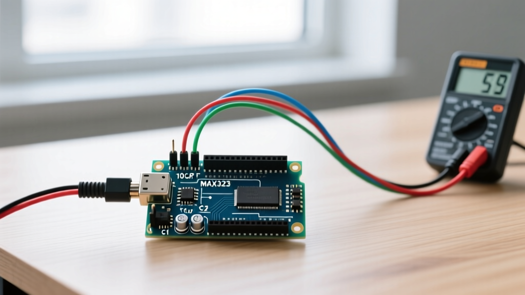
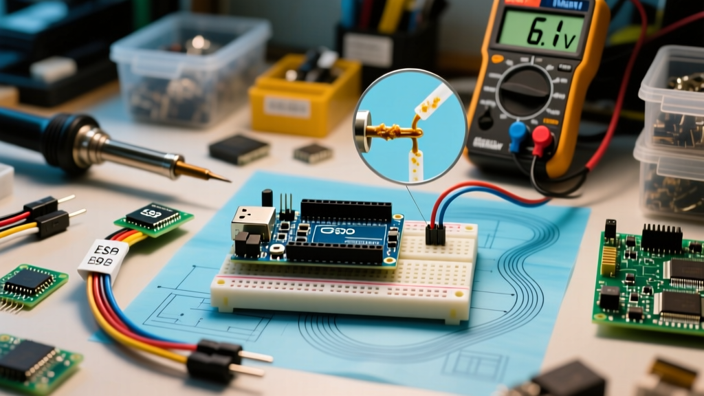
When a maker's project starts exhibiting bizarre behavior—random reboots, corrupted EEPROM data, or unexplained sensor drift—the immediate instinct is often to blame the code. However, as any seasoned embedded systems engineer will tell you, the root cause is frequently physical. Specifically, diagnosing voltage in Arduino circuits reveals that power instability is responsible for over 60% of 'unexplainable' microcontroller faults.
Whether you are working with a classic ATmega328P-based Uno R3, a modern Renesas RA4M1-powered Uno R4 Minima, or an ESP32-S3 DevKit, microcontrollers are incredibly sensitive to power rail fluctuations. A sag of just a few hundred millivolts can trigger a Brown-out Detection (BOD) reset, cause the ADC reference to drift, or push the logic levels into an undefined metastable state. In this comprehensive diagnostic guide, we will bypass generic advice and dive deep into the exact methodologies, tools, and electrical principles required to isolate and fix voltage-related errors in your Arduino projects.
The Anatomy of an Arduino Power Failure
To troubleshoot effectively, you must understand the power architecture of your specific board. Older 5V Arduino boards (like the Uno R3 and Mega 2560) rely on an NCP1117ST50T3G linear voltage regulator to step down the barrel jack input (Vin) to 5V. This architecture is highly inefficient and prone to thermal shutdown when drawing more than 200mA at higher input voltages.
Conversely, modern boards released in the mid-2020s, such as the Arduino Uno R4 series and most ESP32 variants, utilize high-efficiency synchronous buck converters (like the AP63203 or similar integrated DC-DC modules). While these handle higher currents without overheating, they introduce high-frequency switching noise that can severely impact sensitive analog readings if not properly filtered. Understanding which regulator topology your board uses is the first step in targeted error diagnosis.
The Danger of Brown-out Detection (BOD) and EEPROM Corruption
The ATmega328P features a hardware Brown-out Detection (BOD) circuit. By default, the BOD threshold on most 5V Arduino bootloaders is set to 2.7V. If the VCC rail drops below this threshold, the MCU is held in reset. However, a critical edge case occurs when the voltage sags to around 3.5V. At this level, the CPU may attempt to execute instructions, but the SRAM and flash memory become unstable. If an EEPROM write operation is triggered during this 'brown-out twilight zone', the data will be corrupted, and the program counter may jump to an arbitrary memory address, causing a hard lockup. According to the official Microchip ATmega328P datasheet, ensuring VCC remains strictly above 4.5V during active write cycles is mandatory for data integrity.
Symptom Matrix: Matching Errors to Voltage Faults
Use the following diagnostic matrix to quickly map your project's erratic symptoms to their most likely power-related root causes.
| Observed Symptom | Affected Rail | Diagnostic Tool | Probable Root Cause |
|---|---|---|---|
| Random resets under motor load | 5V Logic (VCC) | Oscilloscope (Single Shot) | Back-EMF causing VCC sag below 4.3V |
| avrdude timeout / Upload failure | USB VBUS | Inline USB Power Meter | Cable resistance dropping VBUS below 4.35V |
| Analog sensor readings drifting | VREF (AREF) | Precision Multimeter (4.5 digit) | High-frequency noise on the 5V reference rail |
| Board shuts down after 3 minutes | Vin to 5V | Thermal Camera / IR Thermometer | Linear regulator thermal shutdown (150°C) |
| I2C devices randomly drop off bus | 3.3V / 5V Logic | Logic Analyzer | Ground bounce violating I2C voltage thresholds |
Step-by-Step Diagnostic Workflow
When voltage in Arduino circuits is suspected, follow this strict isolation procedure to identify the exact point of failure.
Step 1: The USB VBUS Drop Test
Upload failures and random serial disconnects are often blamed on the CH340 or ATmega16U2 USB interface chips, but the real culprit is usually the USB cable. The USB 2.0 specification mandates a voltage tolerance of 4.75V to 5.25V. Cheap, mass-produced cables often use 28 AWG or even 30 AWG wire for the power lines, which possess high resistance. When your Arduino draws 150mA, a 6-foot 28 AWG cable can drop the voltage at the board's VBUS pin to a mere 4.2V, causing the onboard voltage regulator to drop out.
- Action: Insert an inline USB tester (such as a MakerHawk or RuiDeng UM25C) between your PC and the Arduino.
- Pass Criteria: Voltage must remain above 4.75V under maximum operational load (e.g., when all LEDs and sensors are active).
- Fix: Replace the cable with a certified 22 AWG or 24 AWG silicone USB cable.
Step 2: Probing the Logic Rails Under Dynamic Load
A standard digital multimeter (DMM) samples voltage roughly 2 to 3 times per second. It is completely useless for catching microsecond voltage sags caused by a relay switching or a servo motor starting. To properly diagnose voltage in Arduino projects, you must use an oscilloscope or a DMM with a 'Min/Max' capture function capable of recording 1-millisecond peaks.
- Connect your oscilloscope ground clip directly to the Arduino's GND header pin, not the USB port shield.
- Connect the probe tip to the 5V header pin.
- Set the trigger mode to 'Single' and the trigger level to 4.6V (falling edge).
- Execute the code that causes the reset. If the scope captures a dip below 4.6V coinciding with the reset event, you have confirmed a dynamic voltage sag.
Step 3: Evaluating the Vin and Barrel Jack Thermal Limits
If you are powering a classic Uno R3 via the barrel jack with a 12V wall adapter and drawing 300mA from the 5V pin, you are forcing the onboard NCP1117 linear regulator to dissipate 2.1 Watts of heat ((12V - 5V) * 0.3A = 2.1W). The SOT-223 package has a junction-to-ambient thermal resistance of roughly 53°C/W. This means the regulator's internal junction temperature will rise by over 110°C above ambient, instantly triggering its internal thermal shutdown protection. The board will appear to randomly reboot as the regulator cools and restarts.
Expert Rule of Thumb: When using the barrel jack or Vin pin on a board with a linear regulator, never exceed an input voltage of 9V if your 5V current draw exceeds 100mA. For higher currents, bypass the onboard regulator entirely and supply regulated 5V directly to the 5V header pin.
Advanced Edge Cases: Ground Bounce and Inductive Kickback
Sometimes, the 5V rail looks perfectly clean on an oscilloscope, yet the Arduino still resets. In these cases, the issue is not a drop in VCC, but a spike in GND—a phenomenon known as ground bounce. When a high-current inductive load (like a relay coil or a DC motor) switches off, the collapsing magnetic field generates a massive voltage spike (back-EMF). If the load shares a ground return path with the Arduino's logic, this spike elevates the local ground potential. To the microcontroller, a 1.5V ground spike looks exactly like a 3.5V VCC sag, triggering a brown-out reset.
To resolve this, you must implement strict star-grounding topology and use flyback diodes. A standard 1N4007 rectifier diode placed in reverse bias across the relay coil will safely clamp the inductive kickback. Additionally, ensure that high-current ground returns do not pass through the Arduino's breadboard ground rails; route them directly back to the power supply's negative terminal.
Real-World Case Study: The Servo Power Trap
A ubiquitous error in the maker community involves powering multiple SG90 micro servos directly from the Arduino's 5V pin. A single SG90 can draw up to 700mA during stall conditions. If your sketch commands four servos to move simultaneously, the instantaneous current demand can spike to 2.8A.
The Arduino's USB port polyfuse is typically rated for 500mA, and the onboard linear regulator is rated for 1A (but thermally limited to ~200mA at higher Vin voltages). Attempting to pull 2.8A through the Arduino's 5V trace will cause a catastrophic voltage drop, resetting the MCU, and potentially melting the PCB trace or tripping your PC's USB port overcurrent protection.
The Correct Diagnostic and Repair Protocol
Instead of relying on the Arduino's internal power routing, use a dedicated step-down (buck) converter. The LM2596 or the more modern, highly efficient MP1584EN modules can easily handle 3A to 5A of continuous current. As detailed in the Texas Instruments LM2596 datasheet, these switching regulators require proper input and output decoupling. Wire the high-current servo power directly from the buck converter's output, and connect only the signal wires and a common ground to the Arduino. This completely isolates the sensitive logic voltage from the noisy, high-current motor loads.
Summary of Best Practices for Power Integrity
Diagnosing voltage in Arduino ecosystems requires moving beyond simple 'is it plugged in' checks. By understanding the physical limitations of linear regulators, the realities of USB cable resistance, and the destructive nature of inductive kickback, you can design robust systems that operate flawlessly. Always measure under dynamic load, use appropriate decoupling capacitors (100nF ceramic across VCC/GND near every IC), and respect the current limits of your board's power traces. For further reading on isolating high-current loads, the Adafruit Motor Shield power guide provides excellent visual examples of separating logic and motor power domains.