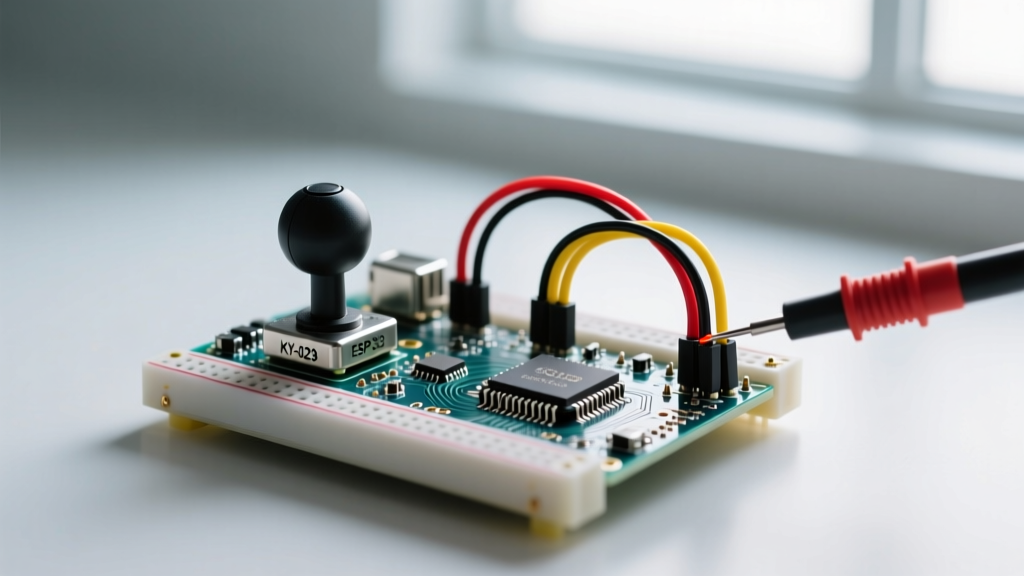

The tone() function is often the second tool a maker learns after digitalWrite(). Generating a square wave to drive a piezo buzzer or a small speaker seems trivial—until your project scales. When integrating audio feedback into multi-sensor environments, motor controllers, or wireless arrays, tone Arduino implementations frequently fail. Symptoms range from silent pins and distorted static to complete microcontroller brownouts and silent PWM failures on unrelated components.
This guide bypasses basic syntax tutorials and dives straight into the silicon-level and architectural conflicts that cause tone() errors. We will diagnose hardware timer collisions, address the massive ESP32 LEDC API overhauls standard in 2026, and solve the analog hardware edge cases that destroy audio fidelity.
The Anatomy of a tone() Failure
To diagnose a failure, you must understand the underlying peripheral. On classic 8-bit AVR boards like the Uno R3 (ATmega328P), the tone() function does not use dedicated audio hardware. Instead, it hijacks Timer2 to generate an interrupt-driven square wave. Every time the timer overflows, it toggles the state of the target GPIO pin.
Because Timer2 is a shared resource, any other library or function relying on it will immediately conflict. According to the official Arduino Language Reference, tone() is inherently blocking to other Timer2 operations, and only one tone can be generated at a time across the entire MCU. If you attempt to call tone() on a second pin without calling noTone() on the first, the second call is simply ignored.
Diagnostic Matrix: Top 4 Tone Arduino Errors
Use this matrix to quickly isolate the root cause of your audio failure based on the primary symptom.
| Symptom | Root Cause | Diagnostic Step | Resolution |
|---|---|---|---|
| No sound on Pin 3 or 11 | Timer2 PWM conflict | Check for analogWrite() on pins 3/11 |
Move PWM to Timer1 pins (9, 10) |
| Distorted/Static Audio | Piezo capacitive spike / Ground bounce | Measure voltage drop under load | Add 100Ω - 330Ω series resistor |
| ESP32 Compilation Error | Deprecated LEDC API | Check ESP32 Core version (v3.x+) | Migrate to ledcAttach() |
| Intermittent MCU Resets | Inductive flyback voltage | Scope the pin on decay edge | Add 1N4148 flyback diode |
The Timer2 Trap: PWM Interference on Pins 3 and 11
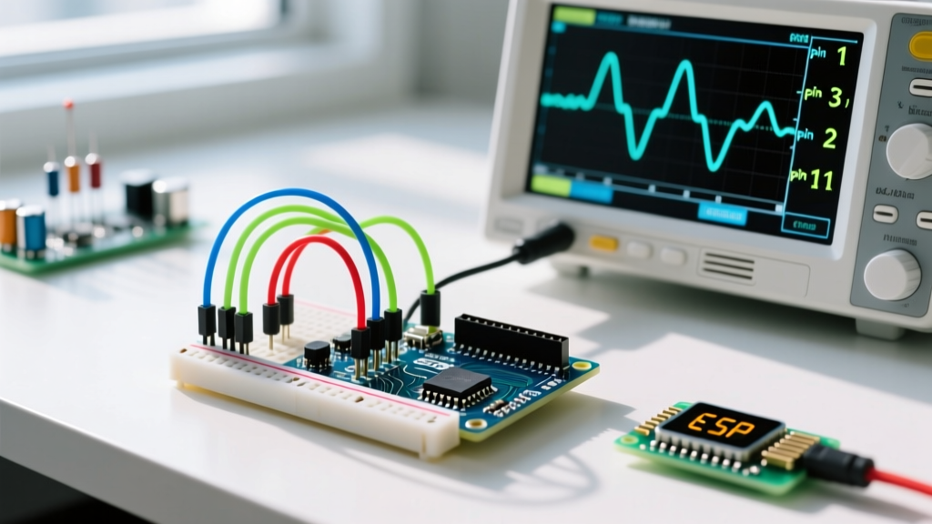
The most common tone Arduino error occurs when makers attempt to use Pulse Width Modulation (PWM) alongside audio feedback. On the ATmega328P, Timer2 controls the hardware PWM for Pin 3 (OC2B) and Pin 11 (OC2A).
The Collision Scenario
Imagine you are building a robotic rover. You use Pin 11 to control a motor's speed via analogWrite(11, 150). Later, a collision sensor triggers, and you call tone(8, 1000, 200) to sound an alarm on Pin 8.
- What happens: The
tone()function reconfigures Timer2 to generate a 1000Hz interrupt. This instantly destroys the PWM timing on Pin 11. Your motor either stops, stutters wildly, or jumps to full speed untilnoTone()is called and the PWM registers are restored. - The Fix: Never mix
tone()withanalogWrite()on Pins 3 or 11. Consult the Secrets of Arduino PWM guide to map your motor control or LED fading to Timer1 (Pins 9 and 10) or Timer0 (Pins 5 and 6). Note that altering Timer0 will breakmillis()anddelay(), making Timer1 the safest alternative.
ESP32 Architecture Shifts: Navigating the Core v3.x LEDC Overhaul
If you have migrated from AVR to the ESP32 ecosystem, you have likely encountered severe compilation errors or runtime panics when using audio functions. The ESP32 does not use AVR timers; it uses the LEDC (LED Control) peripheral to generate square waves.
The Deprecation of ledcSetup()
Prior to 2024, generating a tone on an ESP32 required a cumbersome three-step process: assigning a channel, setting up the channel with ledcSetup(), attaching the pin, and finally writing the tone.
As of 2026, the standard ESP32 Arduino Core (v3.x) has completely deprecated the channel-based LEDC API in favor of a direct pin-mapping architecture that mirrors standard Arduino functions. If your legacy code uses ledcSetup(), it will fail to compile.
The Modern ESP32 Tone Implementation
According to the Espressif Arduino LEDC API Documentation, the correct, modern implementation bypasses manual channel assignment entirely:
// ESP32 Core v3.x+ Standard Implementation
const int buzzerPin = 18;

void setup() {
  // Attach the pin directly to the LEDC peripheral
  // Parameters: pin, frequency (Hz), resolution (bits)
  ledcAttach(buzzerPin, 5000, 8);
}

void loop() {
  // Generate a 1000Hz tone
  ledcWriteTone(buzzerPin, 1000);
  delay(500);

  // Silence the pin
  ledcWriteTone(buzzerPin, 0);
  delay(500);
}
Diagnostic Tip: If your ESP32 produces a faint, high-pitched whine instead of the intended frequency, verify your resolution parameter. An 8-bit resolution at 5000Hz base frequency provides the cleanest square wave for standard piezo buzzers. Using 10-bit or 12-bit resolution at high base frequencies can exceed the ESP32's APB clock divider limits, resulting in silent failures or corrupted waveforms.
Hardware Edge Cases: Impedance, Capacitance, and Flyback Voltage
Software diagnostics mean nothing if the physical circuit is flawed. Microcontrollers are not audio amplifiers; they are logic devices rated for strict current limits. Driving audio loads directly from a GPIO pin introduces severe hardware edge cases.
The Piezo Capacitance Problem
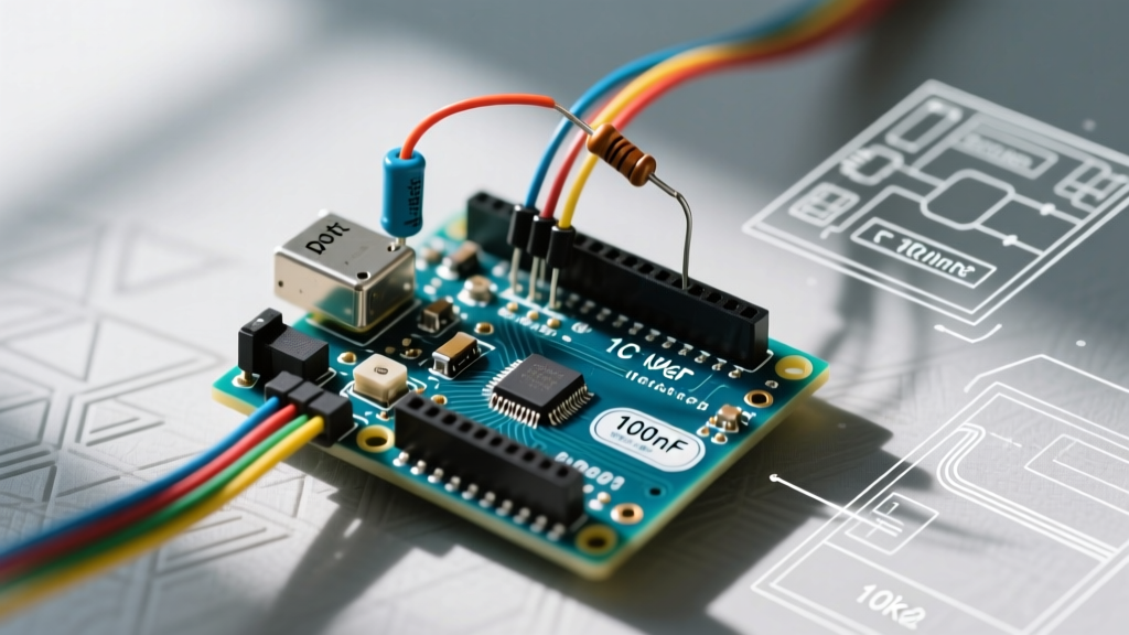
Piezo buzzers are essentially capacitors. When a GPIO pin transitions from LOW to HIGH, it must instantly charge this capacitor. This creates a massive, microsecond current spike that can exceed the 40mA absolute maximum rating of an ATmega328P GPIO pin.
Expert Insight: If your Arduino randomly resets or the onboard voltage regulator overheats precisely when a tone starts playing, you are experiencing ground bounce and brownout caused by piezo charging spikes.
The Fix: Always place a 100Ω to 330Ω series resistor between the GPIO pin and the piezo buzzer. This limits the inrush current to safe levels (approx. 15mA) while barely affecting the acoustic volume of the high-impedance piezo element.
Inductive Flyback on Magnetic Speakers
If you are driving a small 8Ω magnetic speaker instead of a piezo, you are dealing with an inductive load. When the tone() function stops (or during the LOW phase of the square wave), the collapsing magnetic field in the speaker coil generates a reverse voltage spike (flyback voltage). This spike can easily exceed 50V, instantly destroying the MCU's GPIO silicon.
The Fix: Wire a 1N4148 or 1N4001 flyback diode in parallel with the speaker, with the cathode (striped end) facing the GPIO pin and the anode facing Ground. This provides a safe recirculation path for the inductive kickback.
Step-by-Step Diagnostic Flowchart
When you upload your sketch and hear nothing, follow this exact diagnostic sequence before rewriting your code:
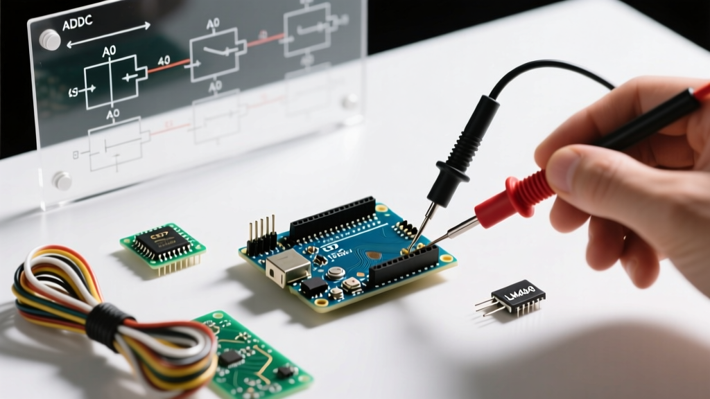
- Verify the Load: Disconnect the buzzer. Use a multimeter set to AC Voltage (or an oscilloscope) to probe the GPIO pin while the
tone()function should be active.- If you read ~2.5V AC (or see a 0-5V square wave): The MCU is fine; your buzzer is dead or wired incorrectly.
- If you read 0V: Proceed to Step 2.
- Check Timer Conflicts: Comment out all
analogWrite(),Servolibrary calls, and IR receiver libraries (like IRremote, which heavily relies on Timer2). Recompile. If the tone works, you have a timer collision. - Verify Pin Capabilities: Ensure you are not calling
tone()on a pin that is strictly an input-only pin or a pin shared with the SPI/I2C bus that is currently actively polling a sensor. - Check the Duration Parameter: If using
tone(pin, freq, duration), remember that the function is non-blocking. If your code immediately enters a deep sleep or resets the pin state in the next microsecond, the tone will never audibly manifest.
Summary
Resolving tone Arduino errors requires looking beyond the IDE's serial monitor. By understanding the rigid hardware timer allocations of the ATmega328P, adapting to the modern ESP32 LEDC API standards, and respecting the electrical limits of GPIO pins with proper series resistance and flyback protection, you can integrate reliable, crash-free audio feedback into any embedded system.