
Why the Opta Lite (AFX00078) Defies Standard Arduino Troubleshooting
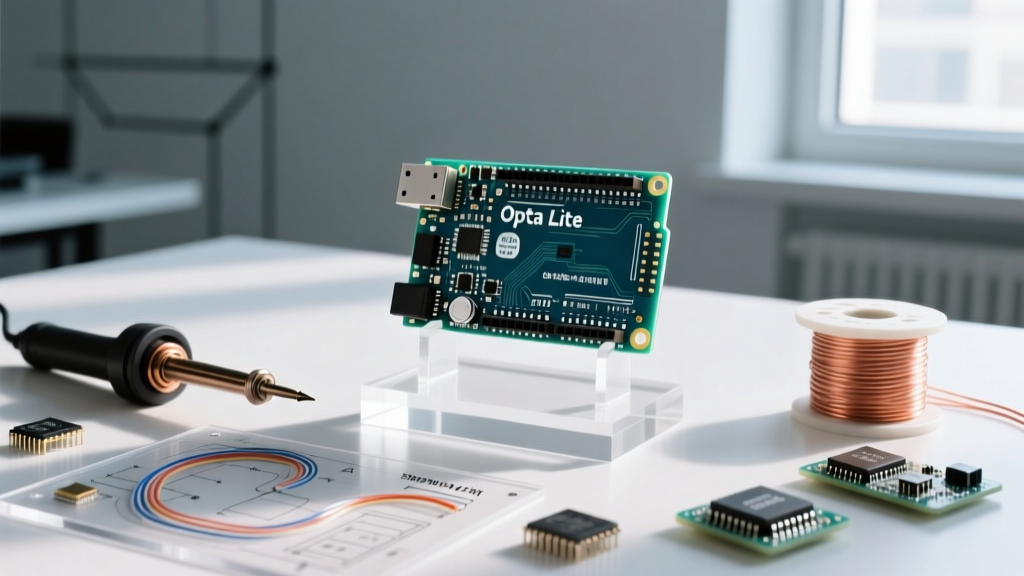
The Arduino Opta Lite (SKU: AFX00078) represents a fundamental shift in the Arduino ecosystem. Co-developed with Finder, this micro-PLC and IoT gateway is not a simple 8-bit AVR microcontroller. It is built around the STMicroelectronics STM32H747XI, a dual-core powerhouse featuring a 480 MHz Cortex-M7 and a 240 MHz Cortex-M4. Priced around $195 USD in 2026, the Opta Lite is the most accessible entry point into the Opta lineup, omitting the mechanical relays and Wi-Fi/RS485 modules found in its more expensive siblings in favor of solid-state transistor outputs and native Ethernet.
Because it bridges the gap between traditional C++ Arduino sketches and IEC 61131-3 industrial PLC logic, troubleshooting the Opta Lite requires an understanding of embedded RTOS architectures, dual-core memory partitioning, and industrial 24V DC power dynamics. Standard Arduino troubleshooting steps—like simply unplugging the USB cable or selecting a different COM port—often fail when dealing with the Opta's Mbed OS bootloader and industrial I/O shielding. This guide provides deep-dive, actionable solutions for the most critical failure modes encountered by automation engineers and advanced makers.
Diagnostic Matrix: Symptom-to-Solution Mapping
Before opening your enclosure or rewriting your sketch, cross-reference your device's physical behavior with this diagnostic matrix. The Opta's onboard status LEDs (specifically LED_D0 and the RGB user LEDs) provide vital telemetry regarding the STM32H747XI's boot state.
| Symptom | LED Indicator State | Root Cause | Primary Resolution |
|---|---|---|---|
| COM Port vanishes immediately after sketch upload | LED_D0 solid Red, then off | Hard fault in Mbed OS USB CDC stack due to blocking code in setup() | Double-tap RESET to enter DFU mode; refactor blocking loops |
| Device ignored by Arduino PLC IDE | RGB LED pulsing Cyan | Flash memory partition mismatch; Arduino IDE overwrote PLC runtime | Perform full QSPI flash wipe via STM32CubeProgrammer |
| Outputs (Q1-Q4) fail to switch external loads | Status LEDs for outputs illuminate, but no continuity | Missing 24V DC auxiliary power or blown internal solid-state MOSFET | Verify 24V rail on terminal block; test with purely resistive load |
| Ethernet DHCP timeout / Network hang | Link LED on RJ45 jack off or flickering erratically | LAN8742A PHY chip initialization race condition on cold boot | Implement 500ms hardware delay in setup() before Ethernet.begin() |
Fix 1: Recovering from 'Vanishing COM Port' and Mbed OS Crashes
The most frequent issue reported by engineers migrating from the Arduino Uno or Nano to the Opta Lite is the 'vanishing COM port.' Unlike older boards that maintain a persistent hardware USB-to-Serial bridge, the Opta Lite utilizes the STM32's native USB peripheral, managed by the Mbed OS real-time operating system. If your C++ sketch encounters a hard fault, enters an infinite blocking loop without yielding to the RTOS, or attempts to access unmapped memory, the Mbed OS USB stack crashes. The host PC immediately drops the COM port.
The Double-Tap Recovery Sequence
To recover the board without resorting to external ST-Link programmers, you must force the Cortex-M7 core into its ROM bootloader (DFU mode).
- Locate the physical RESET button on the front panel of the Opta Lite.
- Press and release the RESET button twice in rapid succession (within 500 milliseconds).
- Observe the onboard LED. If successful, the LED will pulse a slow, breathing green or amber, indicating the device is in bootloader mode.
- Open the Arduino IDE 2.x. A new COM port (or DFU device node) will appear in the Tools menu.
- Upload a known-safe, non-blocking blink sketch to restore standard USB CDC functionality.
Preventing RTOS Starvation
To prevent this from recurring, never use delay() in complex loops that require network or USB stack maintenance. Instead, utilize the mbed::Ticker class or non-blocking millis() timing. For deep technical reference on the underlying OS, consult the Arduino Mbed OS Core Repository, which details how the RTOS allocates thread priorities for USB management.
Fix 2: Resolving Arduino IDE vs. PLC IDE Toolchain Collisions
The Opta Lite is unique because it supports two entirely different programming paradigms: the standard Arduino IDE (C/C++) and the Arduino PLC IDE (IEC 61131-3 Ladder, FBD, ST). A critical edge case occurs when a user programs the device via the standard Arduino IDE, and later attempts to deploy a PLC logic sketch. The device will appear 'bricked' or unresponsive to the PLC IDE.
Understanding the Flash Partition Map
The STM32H747XI features 2MB of internal Flash. The Arduino PLC IDE reserves a specific memory partition (typically starting at 0x08040000) for the IEC 61131-3 runtime engine and the user logic. When you upload a standard Arduino sketch via the Arduino IDE using the 'Arduino Mbed OS Opta Boards' package, it often overwrites the entire flash bank, erasing the proprietary PLC bootloader and runtime environment.
To restore PLC functionality, you cannot simply 'upload' a new PLC sketch. You must re-flash the Opta firmware bundle. According to the Official Arduino Opta Hardware Documentation, this requires downloading the latest Opta firmware `.bin` package from the Arduino PLC IDE support portal and using the STM32CubeProgrammer utility to write the binary directly to the primary flash address (0x08000000) via the DFU interface established in Fix 1.
Fix 3: 24V Power Rail Brownouts and Transistor Output Faults
The 'Lite' in Opta Lite signifies the absence of mechanical relays. Instead, the AFX00078 model utilizes solid-state transistor outputs (Q1 through Q4), rated for 2A per channel at 24V DC. While solid-state outputs offer vastly superior lifespan and switching speeds for PWM applications, they introduce specific troubleshooting scenarios regarding inductive kickback and power rail stability.
The Inductive Load Trap
If your Opta Lite is resetting randomly when an output switches off, you are likely experiencing an inductive voltage spike. Because the Opta Lite lacks the internal flyback diodes found in some traditional mechanical relay PLCs, switching off inductive loads (like contactor coils, solenoid valves, or small DC motors) generates a reverse EMF spike that can exceed the 40V breakdown limit of the internal MOSFETs, triggering the STM32's internal brownout reset (BOR) or permanently damaging the output channel.
- Rule of Thumb: Always wire an external 1N4007 flyback diode in reverse parallel across any inductive load connected to the Opta Lite's transistor outputs.
- Power Supply Sizing: The Opta's internal logic requires roughly 200mA at 24V. If you are powering external sensors from the same 24V bus, ensure your DIN-rail power supply (e.g., Mean Well HDR-30-24) can handle the combined inrush current. A 10% voltage dip on the 24V rail during actuator engagement will cause the Cortex-M7 to fault.
Fix 4: Ethernet PHY (LAN8742A) Initialization Hangs
The Opta Lite features native 10/100 Ethernet via an onboard Microchip LAN8742A PHY chip. A common failure mode in industrial enclosures is the Ethernet stack hanging during a cold boot, particularly when connected to unmanaged industrial switches that take several seconds to negotiate link states.
The Mbed OS network stack expects the PHY to respond within a strict timeout window. If the switch is still in its own boot sequence, the Opta's DHCP client will fail silently, leaving the device disconnected. To fix this, inject a hardware-level delay and a manual link-check loop in your C++ setup routine before calling network functions:
delay(1500); // Allow PHY and external switch to stabilize
while (Ethernet.linkStatus() == LinkOFF) {
  delay(100);
}
Ethernet.begin(mac, ip);
For comprehensive specifications on the STM32H747XI's internal MAC and its RMII interface routing, refer to the STMicroelectronics STM32H747XI Product Page and its associated reference manual.
Expert Insight: Dual-Core Memory Boundaries
When writing advanced firmware for the Opta Lite, remember that the Cortex-M7 (Mbed OS/Arduino logic) and the Cortex-M4 (often reserved for deterministic PLC tasks or motor control) share RAM but have distinct memory access controllers (MPU). If you attempt to pass pointers to dynamically allocated memory between cores without using the OpenAMP inter-processor communication (IPC) framework, the M4 core will trigger a hard fault. Always use statically allocated shared memory buffers mapped in the SRAM3 region for cross-core data exchange.
Summary: Best Practices for 2026 Deployments
Troubleshooting the Arduino Opta Lite requires abandoning the 'plug-and-play' mindset of hobbyist boards and adopting an industrial automation methodology. By respecting the Mbed OS thread scheduling, maintaining strict flash partition boundaries between the Arduino and PLC toolchains, and properly conditioning your 24V DC power and inductive loads, the AFX00078 proves to be an incredibly robust, sub-$200 platform for edge computing and industrial IoT. Always keep a USB-C cable and the STM32CubeProgrammer utility on hand for low-level DFU recovery, ensuring your deployment downtime is measured in minutes, not days.