
The "Wrong Architecture" Failure Mode
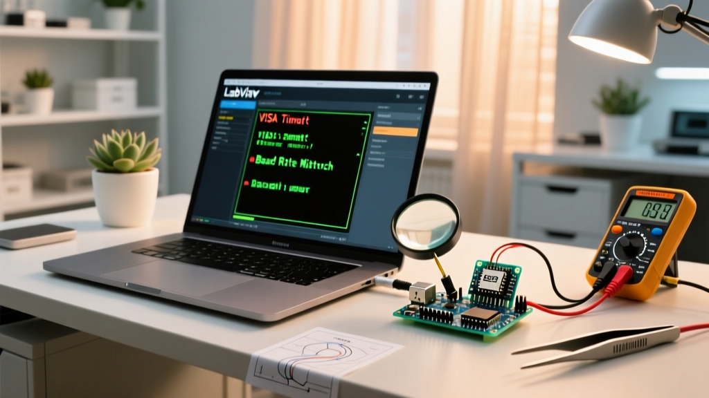
When a DIY electronics project suffers from unexplainable timing jitter, random boot failures, or fried GPIO pins, the root cause is rarely a defective component. More often than not, the failure stems from a fundamental misunderstanding of the difference between Raspberry Pi and Arduino architectures. Makers frequently select a board based on community popularity rather than electrical suitability, leading to severe hardware and software mismatches.
The Raspberry Pi is a single-board computer (SBC) powered by a microprocessor (like the BCM2712 in the Pi 5) running a full Linux operating system. The Arduino is a microcontroller unit (MCU) development board (like the Uno R4 Minima with its Renesas RA4M1 chip) that executes bare-metal C++ code without an underlying OS. When you force a microprocessor to handle hard real-time sensor polling, or force a microcontroller to process heavy computer vision workloads, your project will fail. This troubleshooting guide will help you diagnose these architectural mismatches and implement the correct hardware fixes.
Diagnostic Matrix: Is Your Pi or Arduino Causing the Crash?
Before swapping out components or rewriting thousands of lines of code, use this diagnostic matrix to identify if your symptoms point to an architectural mismatch.
| Symptom / Failure Mode | Likely Culprit | The Architectural Fix |
|---|---|---|
| Microsecond sensor polling yields inconsistent timing (jitter). | Raspberry Pi (Linux OS scheduling latency) | Offload sensor reading to an Arduino via I2C/UART; use Pi only for data logging. |
| Board randomly reboots when servos or motors activate. | Raspberry Pi (Voltage drop below 4.63V triggers PMIC reset) | Isolate motor power supply; use an Arduino for direct PWM motor control. |
| GPIO pins on the main board are unresponsive or physically hot. | Logic Level Mismatch (5V Arduino feeding 3.3V Pi) | Install a bidirectional logic level converter (e.g., TXS0108E) between the boards. |
| Code crashes when handling large image arrays or JSON payloads. | Arduino (SRAM limitations, e.g., 32KB on Uno R4) | Migrate processing to Raspberry Pi (4GB/8GB LPDDR4X RAM) and send simple commands to the MCU. |
Troubleshooting Real-Time Jitter and Latency
One of the most common troubleshooting scenarios in advanced maker projects involves reading high-frequency sensors, such as rotary encoders or ultrasonic flow meters. If you attempt this on a Raspberry Pi using Python or C++, you will inevitably encounter timing jitter.
The Linux Scheduling Problem
The Raspberry Pi runs Linux, which uses the Completely Fair Scheduler (CFS). The OS routinely pauses your user-space script to handle background tasks, network interrupts, or memory management. This results in latency spikes ranging from 50 microseconds to several milliseconds. According to the official Raspberry Pi documentation, the Pi is designed for high-throughput computing, not deterministic real-time I/O.
The Bare-Metal Solution
Conversely, an Arduino Uno R4 executes instructions sequentially on its 48MHz ARM Cortex-M4 core. When you use hardware interrupts via attachInterrupt(), the MCU pauses the main loop and services the interrupt in under 5 microseconds, every single time. If your Pi-based project is failing due to missed encoder pulses, the fix is not to tweak Linux kernel parameters (though the PREEMPT_RT patch can help marginally). The true fix is to wire the encoder directly to an Arduino, count the pulses in hardware, and send the final RPM value to the Pi over a serial connection.
Fixing Power Delivery and Brownout Resets
Power management is another area where the difference between Raspberry Pi and Arduino dictates your troubleshooting approach. A frequent complaint on forums is the Pi randomly shutting down when a peripheral is connected.
Raspberry Pi Power Sensitivity
The Raspberry Pi 5 requires a strict 5V/5A (27W) delivery via USB-C Power Delivery to support full peripheral current. If the voltage at the SoC drops below approximately 4.63V, the onboard DA9098 Power Management IC (PMIC) will trigger a brownout reset to protect the filesystem. Connecting high-draw components like 5V servo motors directly to the Pi's 5V GPIO pin will instantly cause a voltage sag and a system crash.
Arduino Power Tolerance and Thermal Throttling
Arduino boards are far more forgiving with input voltage but suffer from thermal issues. The classic Arduino Uno accepts 7V to 12V via the barrel jack. However, this passes through an onboard linear regulator (like the NCP1117). If you input 12V and draw 200mA from the 5V pin, the regulator must dissipate 1.4W of heat (7V drop × 0.2A). Without a heatsink, the regulator will hit its 150°C thermal shutdown limit, causing the board to reset. The Fix: If your Arduino is resetting under load, measure the input voltage. If it is above 9V, lower it to 7.5V, or bypass the linear regulator entirely by supplying a clean, regulated 5V directly to the 5V pin (bypassing the USB and barrel jack protection).
Resolving GPIO Logic Level Fried Pins
Perhaps the most destructive troubleshooting scenario occurs when makers attempt to combine both boards in a single project without respecting their logic levels. This is where understanding the hardware difference between Raspberry Pi and Arduino becomes a matter of preventing permanent silicon damage.
The 3.3V vs 5V Trap
The Raspberry Pi's BCM2712 SoC operates strictly at 3.3V logic. Its GPIO pins are not 5V tolerant; applying 5V to a Pi GPIO pin will forward-bias the internal ESD protection diodes, causing excessive current flow that permanently destroys the pin or the entire SoC ring. The standard Arduino Uno, however, operates at 5V logic. Connecting a 5V Arduino digital output directly to a 3.3V Raspberry Pi input is a guaranteed way to fry your SBC.
The Hardware Fix: Level Shifting
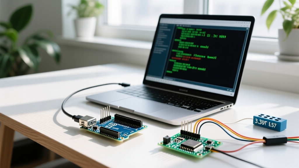
To safely interface a 5V Arduino with a 3.3V Raspberry Pi, you must use a logic level converter. For high-speed or multi-pin setups, the Texas Instruments TXS0108E 8-Bit Bi-directional Voltage-Level Translator is the industry standard. It safely translates signals between the two voltage domains without introducing significant propagation delay. For simple, low-speed I2C communication, a pair of BSS138 N-channel MOSFETs with 10kΩ pull-up resistors on both the 3.3V and 5V sides will safely shift the SDA and SCL lines. Always verify the logic levels with a digital multimeter before connecting the data lines to your Pi.
Step-by-Step Migration Protocol
If you have diagnosed that your current board is fundamentally incapable of handling your project's requirements, follow this migration protocol to transition your hardware safely.
- Audit the I/O Requirements: Count your required digital pins, analog inputs, and hardware interrupt lines. If you need more than 4 hardware interrupts or native analog-to-digital conversion (ADC), you must use an Arduino (or similar MCU). The Raspberry Pi has zero native ADC pins and limited hardware PWM channels.
- Separate the Control from the Compute: Adopt a hybrid architecture. Use the Raspberry Pi for heavy compute tasks (OpenCV image processing, MQTT networking, database logging) and use the Arduino as a dedicated I/O co-processor.
- Establish a Robust Bus: Connect the two boards using I2C or UART. As noted in the Arduino microcontroller overview, I2C is ideal for short-distance, multi-node communication. Ensure you disable the Pi's internal I2C pull-up resistors if your Arduino breakout board already features them, to prevent bus contention.
- Implement Watchdog Timers: Microcontrollers can lock up due to memory leaks or pointer errors. Enable the Arduino's hardware Watchdog Timer (WDT) to automatically reset the MCU if the main loop hangs, ensuring your Pi doesn't lose connection to its sensor network.
Final Verdict: Choosing the Right Tool
Troubleshooting hardware failures often leads back to the initial design phase. The difference between Raspberry Pi and Arduino is not just a matter of software ecosystems; it is a fundamental divergence in electrical engineering paradigms. The Raspberry Pi is a brain—capable of complex thought, networking, and multitasking, but easily distracted from real-time physical interactions. The Arduino is a reflex arc—incapable of complex multitasking, but capable of reacting to physical stimuli with microsecond precision. By diagnosing your project's failure modes against these architectural realities, you can stop fighting the hardware and start building resilient, crash-proof electronic systems.