
Understanding the Mini Arduino Ecosystem
When makers refer to a "mini Arduino," they are typically talking about the Arduino Pro Mini, the Arduino Nano, or generic ATmega328P clone boards designed for compact, embedded projects. Unlike the standard Arduino Uno, these miniaturized boards often omit the onboard USB-to-Serial converter chip to save space, reduce cost, and lower power consumption. In 2026, a generic ATmega328P Pro Mini clone costs between $2.50 and $4.00, while official or premium variants from brands like SparkFun retail around $14.95.
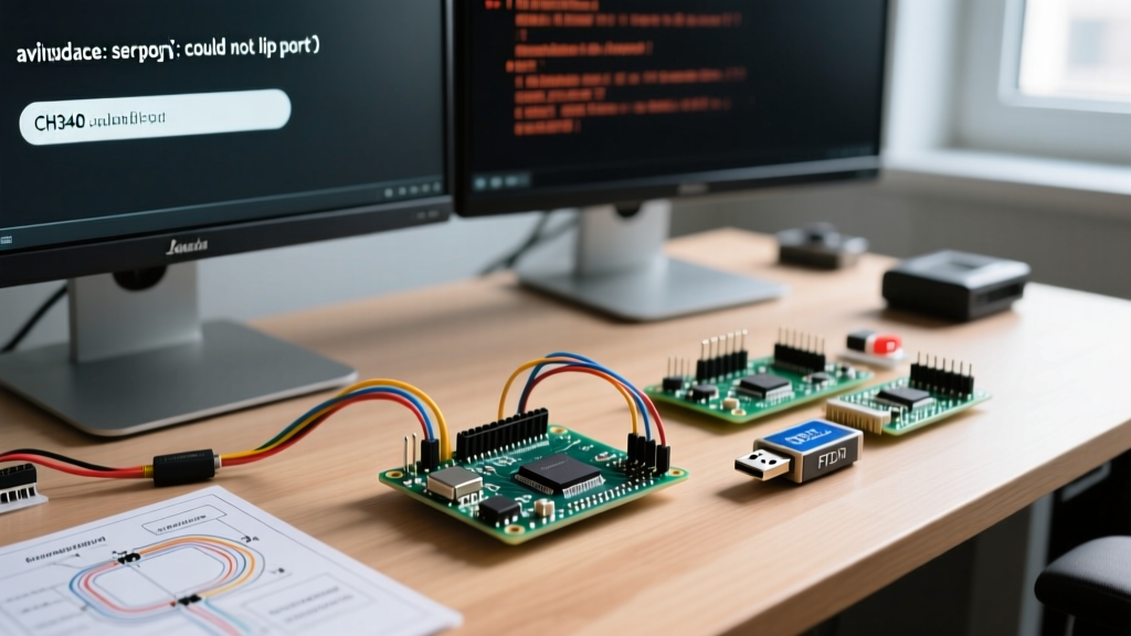
Because the mini Arduino lacks native USB connectivity, uploading a sketch requires an external USB-to-Serial adapter (such as an FTDI FT232RL, CP2102N, or CH340C breakout). This hardware separation is the root cause of 90% of all upload errors. If you are staring at the dreaded avrdude: stk500_getsync() attempt 10 of 10: not in sync: resp=0x00 error in the Arduino IDE, this diagnostic guide will walk you through the exact hardware and software failures causing the issue.
Decoding the 'stk500_getsync' Error Family
The stk500_getsync error is not a single problem; it is a family of communication failures between the Arduino IDE (via AVRDUDE) and the ATmega328P microcontroller's bootloader. The bootloader is a small program residing in the high end of the flash memory that listens for incoming serial data on pins 0 (RX) and 1 (TX) immediately after a reset.
If the bootloader does not receive the correct synchronization handshake within the first 500 milliseconds of a reset, it times out and jumps to the user application code. When this happens, AVRDUDE receives no response or garbage data, resulting in the sync error. According to the Arduino Official Troubleshooting Guide, this timeout is almost always triggered by one of four distinct failure modes: voltage/clock mismatches, serial wiring errors, driver failures, or auto-reset circuit malfunctions.
The 5V/16MHz vs 3.3V/8MHz Bootloader Mismatch
The most insidious cause of mini Arduino upload errors is selecting the wrong board variant in the Arduino IDE. The ATmega328P Pro Mini is manufactured in two distinct hardware configurations:
- 5V / 16MHz: Uses a 5V voltage regulator and a 16MHz crystal oscillator.
- 3.3V / 8MHz: Uses a 3.3V voltage regulator (or direct LiPo input) and an 8MHz crystal oscillator.
If you attempt to upload code to a 3.3V/8MHz board while the IDE is configured for the 5V/16MHz variant, the serial baud rates will be mismatched. The bootloader expects a handshake at 57600 baud, but due to the clock speed difference, the physical hardware interprets the serial timing incorrectly. The result is an immediate not in sync error.
How to Verify Your Clock Speed
Look closely at the top of the silver crystal oscillator on your mini Arduino board. It will have text etched into it. If it reads 16.000, you must select Arduino Pro or Pro Mini (5V, 16 MHz) w/ ATmega328P in the IDE. If it reads 8.000, select the 3.3V/8MHz variant. If your board is a cheap clone with no markings, use a multimeter to check the VCC pin. If it outputs 5V when powered via the RAW pin, it is likely the 16MHz variant.
USB-to-Serial Adapter Wiring and the TX/RX Crossover
Because mini Arduinos rely on external programmers, wiring mistakes are incredibly common. The standard 6-pin FTDI header on a Pro Mini follows this pinout: GRN (DTR), TXO, RXI, VCC, GND, BLK (CTS).
A critical point of confusion arises when connecting generic USB-to-Serial adapters. As detailed in the SparkFun Serial Communication Tutorial, serial communication requires the Transmit (TX) pin of one device to connect to the Receive (RX) pin of the other. However, many cheap CH340G adapters label their pins from the perspective of the adapter, while the Pro Mini labels its pins from the perspective of the microcontroller.
The Golden Rule of Serial Wiring
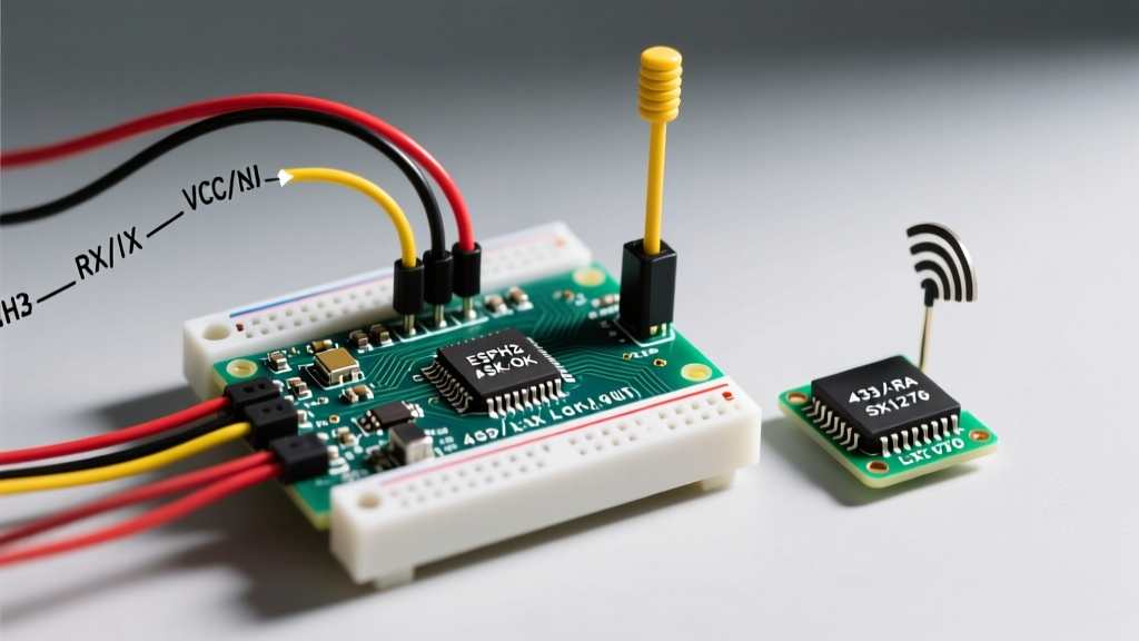
Always wire TX to RX and RX to TX. If your adapter has a TX pin, connect it to the RXI pin on the mini Arduino. If your adapter has an RX pin, connect it to the TXO pin on the mini Arduino. If you wire TX to TX, the boards will simply talk over each other, and the IDE will time out waiting for a response.
Expert Tip: If you are using a 5V FTDI adapter with a 3.3V Pro Mini, you must ensure the adapter's logic level shifter is set to 3.3V. Feeding 5V logic into the 3.3V ATmega328P RX pin can permanently damage the microcontroller's input buffer, resulting in a board that powers on but permanently throws sync errors.
Driver Failures: CH340 vs FT232RL in 2026
The USB-to-Serial adapter you use requires specific drivers to create a virtual COM port. Premium adapters use the FTDI FT232RL chip, which has native driver support in Windows 11, macOS Sonoma/Sequoia, and modern Linux kernels. However, budget adapters (priced around $2.00) use the WCH CH340C or CH341A chips.
If your IDE's Tools > Port menu is grayed out, or your adapter shows up as an "Unknown Device" in the Windows Device Manager, you are experiencing a driver failure. You must download the latest CH340 drivers directly from the WCH official repository or a trusted distributor. On macOS, Apple's security protocols (Gatekeeper) frequently block unsigned CH340 kernel extensions. You may need to manually allow the extension in System Settings > Privacy & Security before the COM port will appear.
The DTR Auto-Reset Failure and Manual Timing Trick
For the bootloader to accept a new sketch, the ATmega328P must be reset exactly as the Arduino IDE finishes compiling and begins the upload process. On a full-sized Uno, the onboard USB chip handles this automatically. On a mini Arduino, this is handled by the DTR (Data Terminal Ready) pin on your external adapter.
The DTR pin connects to the GRN (Green) pin on the Pro Mini. When the IDE initiates an upload, the USB adapter pulses the DTR line low. This pulse passes through a 0.1µF capacitor on the Pro Mini, triggering the RESET pin on the microcontroller. If your adapter lacks a DTR pin, or if the capacitor on your clone board is defective (a common issue on sub-$3 clones), the auto-reset will fail.
The Manual Reset Timing Technique
If your hardware lacks auto-reset capabilities, you can bypass the error using a precise manual timing trick:
- Click the Upload button in the Arduino IDE.
- Watch the black console window at the bottom of the IDE.
- Wait for the compilation to finish and the text
Sketch uses X bytes...to appear. - The exact millisecond you see that text, press and release the physical RESET button on your mini Arduino.
This manually forces the bootloader to start listening right as AVRDUDE begins sending the handshake. It takes a few tries to master the timing, but it is a foolproof workaround for defective DTR circuits.
Power Brownouts and VCC Limits
Another hidden cause of upload errors is a power brownout during the flashing process. The onboard voltage regulators on cheap USB-to-Serial adapters are often rated for a maximum of 50mA. If your mini Arduino project includes sensors, displays, or LEDs that draw more than 50mA, the adapter's voltage will sag below the 4.5V threshold required for the ATmega328P to operate reliably at 16MHz.
When the voltage sags, the microcontroller resets mid-upload, corrupting the handshake. To diagnose this, disconnect all external peripherals from your mini Arduino, leaving only the USB-to-Serial adapter connected. If the upload succeeds with peripherals disconnected, you must power the mini Arduino via its RAW pin using an external 5V/1A buck converter or USB power bank, rather than relying on the adapter's VCC pin.
Mini Arduino Error Diagnostic Matrix
Use the following table to quickly isolate the root cause of your specific upload failure based on the exact error message and hardware behavior.
| Symptom / Error Message | Probable Root Cause | Exact Fix / Action Required |
|---|---|---|
resp=0x00 (Not in sync) | Auto-reset failure or wrong COM port selected. | Use manual reset timing trick; verify DTR wiring to GRN pin. |
resp=0x1e or resp=0x0f | Wrong chip signature; bootloader corrupted or missing. | Re-burn the bootloader using an ISP programmer (e.g., USBasp). |
| Upload succeeds but code runs erratically | 5V/16MHz code uploaded to 3.3V/8MHz board. | Check crystal oscillator; change IDE Board selection to match hardware. |
| IDE Port menu is grayed out | Missing CH340/CP2102 drivers or faulty USB cable. | Install WCH CH340 drivers; swap to a known data-capable USB cable. |
| Upload fails only when sensors are attached | FTDI adapter VCC brownout (exceeding 50mA limit). | Power the mini Arduino via RAW pin with an external 5V power supply. |
| TX/RX LEDs do not flash during upload | Serial wiring crossed incorrectly (TX to TX). | Swap TX and RX wires between the adapter and the mini Arduino. |
When to Re-Burn the Bootloader
If you have verified your wiring, confirmed your clock speed selection, installed the correct drivers, and mastered the manual reset trick, but you are still receiving resp=0x1e or avrdude: Yikes! Invalid device signature errors, your mini Arduino's bootloader is likely corrupted. This frequently happens if the board was subjected to static discharge or if a previous upload was interrupted.
To fix this, you will need an external ISP programmer, such as a $4.00 USBasp or a $17.95 SparkFun AVR Pocket Programmer. As outlined in the SparkFun Pro Mini Hookup Guide, you must connect the ISP programmer to the 6-pin ICSP header (MISO, MOSI, SCK, RST, VCC, GND) and use the Tools > Burn Bootloader function in the Arduino IDE. This wipes the flash memory and reinstalls the Optiboot bootloader, restoring your mini Arduino to factory communication standards.