
The Hidden Bottleneck in IR Prototyping
Integrating an Arduino IR receiver into a project should be a straightforward 10-minute task. In reality, makers frequently lose hours to phantom signals, protocol mismatches, and memory bloat. The root cause is rarely the microcontroller itself; it is an unoptimized workflow that relies on guesswork rather than systematic signal capture and hardware conditioning.
As of 2026, the market is flooded with ultra-cheap, unbranded IR sensors that lack proper automatic gain control (AGC), leading to erratic behavior in modern, electrically noisy environments. To build robust remote-controlled devices, you must shift from a "plug-and-pray" approach to a structured, optimization-first workflow. This guide details the exact hardware selections, power conditioning rules, and software pipelines required to streamline your IR development process.
Hardware Selection Matrix: Stop Buying Blind
The most common workflow killer is selecting the wrong receiver for the host microcontroller's logic level and environmental noise profile. Below is a comparison of the three most prevalent 38kHz receivers on the market.
| Receiver Model | Typical Cost (2026) | AGC & Filtering | Logic Level | Optimal Workflow Use Case |
|---|---|---|---|---|
| VS1838B | $0.10 | Basic / Poor | 5V Tolerant | Low-budget toys, simple NEC remotes in controlled lighting. |
| TSOP38238 (Vishay) | $1.15 | Advanced AGC | 5V Native | High-noise environments, precision robotics, ATmega328P builds. |
| TSOP4838 (Vishay) | $1.30 | Advanced AGC | 3.3V Native | ESP32 / STM32 integration, battery-powered IoT nodes. |
Workflow Rule #1: If you are using an ESP32 or any 3.3V microcontroller, never use the VS1838B or TSOP38238 without a logic level shifter. The 3.3V output from a 5V sensor will eventually degrade the ESP32's GPIO pins, and the sensor's internal pull-ups may not trigger the 3.3V high threshold reliably. Standardize on the TSOP4838 for 3.3V workflows.
The Hardware Workflow: Power Conditioning
"The most common point of failure in IR prototyping isn't the code; it's power supply ripple masquerading as phantom IR pulses."
According to application notes from Vishay Semiconductors, IR receiver ICs are highly sensitive to power supply noise. Switching regulators, LED PWM drivers, and even USB power ripple can cause the receiver's internal AGC to falsely detect a 38kHz carrier. To eliminate hours of software debouncing, implement the following hardware conditioning on every prototype:
- Series Resistor: Place a 100Ω to 470Ω resistor between the VCC source and the receiver's VCC pin.
- Decoupling Capacitor: Place a 4.7µF to 10µF electrolytic capacitor directly across the receiver's VCC and GND pins (physically as close to the IC body as possible).
- Output Pull-up: While most modern receivers have internal pull-ups, adding an external 10kΩ pull-up to the data line ensures crisp rising edges for the microcontroller's interrupt handler.
Implementing this RC filter takes 30 seconds on a breadboard and eliminates 90% of "ghost" signal issues, saving you from writing messy software debounce routines.
Software Workflow: The Universal Dump Pipeline
Do not attempt to write your final application logic until you have definitively captured the remote's protocol. The legacy workflow of guessing between NEC, Sony, and RC5 protocols is obsolete. Instead, use the modern Arduino-IRremote GitHub repository (v4.x or later), which has been heavily optimized for modern AVR and ARM architectures.
Step 1: Non-Blocking Signal Capture
Use the IRrecvDumpV3 example sketch included in the library. This sketch is specifically designed to output the protocol type, hex value, and raw timing arrays to the serial monitor. Crucially, it handles the decoding in the background via interrupts, preventing your main loop from blocking.
Step 2: RAW vs. Decoded Data
When optimizing your workflow, you must decide whether to store decoded hex values or raw timing arrays.
- Decoded Hex: Best for standard TV remotes (NEC, Samsung). Uses minimal memory (4-8 bytes per command).
- RAW Timing: Mandatory for proprietary AC units, ceiling fans, and complex HVAC remotes that use rolling codes or burst patterns that do not fit standard protocol definitions. Requires more SRAM (often 100+ bytes per command).
For an exhaustive breakdown of how these protocols structure their leader pulses and bit frames, the San Bergmans IR Knowledge Base remains the definitive industry reference for understanding the underlying timing mechanics.
Advanced Debugging: Logic Analyzer Integration
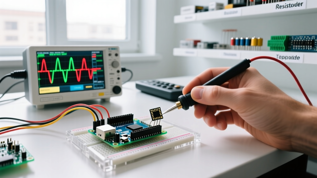
When your Arduino IR receiver setup fails to decode a signal, do not blindly tweak library settings. Connect a $15 USB Logic Analyzer (such as a Saleae clone) to the receiver's data pin and use PulseView (Sigrok) to visualize the waveform. This is the ultimate workflow optimization for edge cases.
What to Look For in PulseView:
- Carrier Leakage: If you see high-frequency jitter on the demodulated output, your sensor's internal filter is failing (common in cheap VS1838B clones under fluorescent lighting).
- Timing Drift: Measure the "Leader Pulse" (e.g., 9ms for NEC). If it measures 7.5ms, you are likely dealing with a variant protocol or a remote with a failing ceramic resonator.
- Inverted Logic: Some specific receiver modules (often marked with an 'S' suffix) output HIGH when receiving IR, rather than the standard LOW. The logic analyzer will reveal this inversion instantly, allowing you to set
IR_RECV_PIN_INVERTEDin your code.
Memory Optimization: The TinyIR Alternative
If your workflow involves constrained microcontrollers like the ATtiny85 or ATmega328P where SRAM is at a premium, the full IRremote library is overkill. It consumes significant flash and requires dedicated hardware timers, which can conflict with PWM motor control or audio generation libraries.
Instead, integrate TinyIR (included in the IRremote v4+ package). TinyIR uses Pin Change Interrupts (PCINT) rather than hardware timers, freeing up Timer1 and Timer2. It is specifically optimized to decode NEC and FAST protocols using less than 500 bytes of flash and minimal RAM, making it the superior choice for wearable IR projects or compact custom PCBs.
Troubleshooting Matrix: Common Edge Cases
Keep this matrix handy to rapidly diagnose workflow interruptions without resorting to forum searches.
| Symptom | Root Cause | Workflow Fix |
|---|---|---|
| Random phantom codes when no remote is pressed | Power supply ripple / Missing decoupling | Add 100Ω series resistor + 4.7µF capacitor on VCC. |
| Works on Uno, fails intermittently on ESP32 | 3.3V logic threshold mismatch | Switch to TSOP4838 (3.3V native) or use a level shifter. |
| Incomplete frames / dropped bits | Fluorescent LED ballast interference (50/60Hz noise) | Physically shield sensor with heat-shrink tubing; avoid VS1838B. |
| Library conflicts with Servo.h or Tone.h | Hardware Timer1/Timer2 collision | Migrate to TinyIR or configure IRremote to use Timer3 (if available). |
Conclusion
Optimizing your Arduino IR receiver workflow is about eliminating variables. By standardizing on high-quality sensors like the Vishay TSOP series, implementing mandatory RC power conditioning, and utilizing non-blocking dump utilities paired with logic analyzer verification, you transform IR integration from a frustrating guessing game into a precise, repeatable engineering process. For further hardware integration tips, the Adafruit IR Sensor Guide provides excellent visual references for breadboard wiring and physical shielding techniques. Stop fighting phantom signals and start building reliable remote-controlled systems.