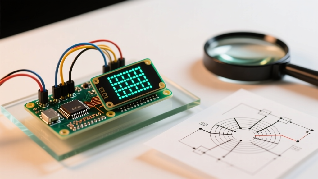

Implementing Conway's Game of Life on a microcontroller is a rite of passage for embedded systems enthusiasts. However, porting this classic cellular automaton to resource-constrained hardware often results in a frustrating loop of random reboots, severe display flickering, and logic-breaking edge artifacts. If your game of life arduino project is struggling to maintain a smooth refresh rate or crashing mid-simulation, you are likely hitting the physical limits of 8-bit architectures or falling victim to C++ mathematical quirks.
This comprehensive troubleshooting guide dissects the most common failure modes encountered when running cellular automata on AVR and ESP-based boards, providing exact code corrections, hardware upgrades, and memory optimization techniques to get your simulation running flawlessly.
The SRAM Bottleneck: Why Your ATmega328P Crashes
The most frequent reason a Game of Life sketch fails to compile or randomly reboots on an Arduino Uno or Nano is Static Random Access Memory (SRAM) exhaustion. The ATmega328P microcontroller possesses a mere 2,048 bytes of SRAM. A standard 128x64 pixel SSD1306 OLED display requires a 1,024-byte frame buffer just to store the screen state before pushing it over I2C.
If you naively declare your cellular grid using standard integer or byte arrays, you will instantly overflow the memory. For a 64x32 grid, using a 2D byte array (byte grid[64][32]) consumes 2,048 bytes per generation. Since the Game of Life requires calculating a 'next generation' based on the 'current generation', you need two arrays, totaling 4,096 bytes—double the Uno's total capacity.
The Fix: Bitwise Memory Packing
To resolve this, you must pack the grid state so that each cell consumes exactly one bit rather than eight. By using bitwise operations, a 64x32 grid requires only 256 bytes per generation (512 bytes total for both current and next states). According to the Arduino Memory Guide, optimizing SRAM is critical for stability on 8-bit boards.
Use the following bitwise logic to set and read cell states in a 1D byte array:
- Set Cell Alive:
grid[x + (y / 8) * WIDTH] |= (1 << (y & 7)); - Set Cell Dead:
grid[x + (y / 8) * WIDTH] &= ~(1 << (y & 7)); - Read Cell State:
bool alive = (grid[x + (y / 8) * WIDTH] >> (y & 7)) & 1;
Eliminating I2C OLED Flicker and Bus Bottlenecks
Even with optimized memory, your display might suffer from severe tearing or a sluggish 5 FPS refresh rate. The default I2C bus speed on the Arduino Wire library is 100kHz. Pushing a 1,024-byte buffer at 100kHz takes approximately 80 milliseconds, capping your theoretical maximum frame rate at around 12 FPS before accounting for the cellular logic computation time.
Pro Tip: Never use thedisplay.clearDisplay()anddisplay.display()functions inside the inner cell-calculation loop. Always compute the entire next generation in the background buffer, then push the buffer to the screen in a single I2C transaction.
Overclocking the I2C Bus
Most modern SSD1306 and SH1106 OLED clones support Fast Mode Plus. You can safely increase the bus speed by adding a single line in your setup() function before initializing the display. The Arduino Wire Library Reference confirms that the setClock() function accepts custom frequencies.
Wire.setClock(800000L); // Sets I2C to 800kHz
This single command reduces the buffer transfer time to roughly 10 milliseconds, instantly tripling your frame rate. If your specific OLED module fails to initialize at 800kHz, drop it back to standard Fast Mode at 400000L.
Fixing Toroidal Grid Edge-Wrapping Logic Errors
In a finite microcontroller simulation, the grid edges must wrap around to create a continuous toroidal topology (a donut shape). If a glider pattern moves off the right edge, it should reappear on the left. However, many makers encounter a bug where patterns hitting the left or top edge cause the simulation to freeze, corrupt memory, or spawn chaotic noise.
The C++ Modulo Trap
The root cause is the behavior of the modulo operator (%) in C++ when handling negative numbers. To check the neighbor to the left of a cell at x = 0, the logical math is (x - 1) % WIDTH. In Python, -1 % 64 correctly evaluates to 63. In C++, -1 % 64 evaluates to -1. Attempting to read grid[-1] causes an out-of-bounds memory read, pulling garbage data from adjacent SRAM variables and corrupting the simulation.
The Solution: Always add the grid dimension before applying the modulo to ensure the operand is strictly positive:
int leftNeighbor = (x - 1 + WIDTH) % WIDTH;int topNeighbor = (y - 1 + HEIGHT) % HEIGHT;
As noted by the ConwayLife Wiki, proper toroidal mapping is essential for preserving the integrity of complex oscillators and spaceships in bounded grids.
Hardware Comparison: When to Upgrade from AVR to ESP32
If you want to run a high-resolution 128x64 grid (requiring 8,192 cells) or push frame rates above 60 FPS, the ATmega328P is no longer viable. Upgrading to a 32-bit architecture eliminates the need for complex bitwise packing and allows for massive grid sizes.
| Feature | Arduino Uno R3 (ATmega328P) | ESP32-DevKitC (WROOM-32) | Arduino Nano 33 IoT (SAMD21) |
|---|---|---|---|
| Architecture | 8-bit AVR | 32-bit Xtensa Dual-Core | 32-bit ARM Cortex-M0+ |
| SRAM | 2 KB | 520 KB | 32 KB |
| Max Grid Size (1-bit) | 64x32 (Barely fits) | 512x256 (Easily) | 128x64 (Comfortable) |
| Clock Speed | 16 MHz | 240 MHz | 48 MHz |
| Typical 2026 Price | $27.00 (Official) | $6.50 (Clone) | $22.00 (Official) |
2026 Component Sourcing and Display Recommendations
When building or upgrading your setup, selecting the right display interface is just as critical as the microcontroller. Here is the current market landscape for cellular automata displays:
- SSD1306 128x64 I2C ($4.50 - $6.00): The standard choice. Ensure you buy the I2C variant with only 4 pins (VCC, GND, SCL, SDA). Avoid the 7-pin SPI versions unless you are willing to wire the MOSI and SCK pins, though SPI will push your frame rate past 100 FPS.
- SH1106 1.3-inch I2C ($5.50 - $7.50): Offers a slightly larger physical screen with the same 128x64 resolution. Note that the SH1106 controller requires a slightly different initialization sequence and does not support hardware horizontal scrolling commands natively in the Adafruit library, which can slow down rendering if not handled via direct memory buffering.
- MakerFocus 1.54-inch TFT LCD (SPI, $12.00): If you want to color-code cell ages (e.g., newborn cells are green, aging cells turn red before dying), a 240x240 SPI TFT driven by an ESP32 is the ultimate 2026 upgrade path, utilizing the TFT_eSPI library for DMA-driven background rendering.
Troubleshooting Matrix: Quick Fixes
Use this diagnostic matrix to quickly identify and resolve lingering issues in your sketch.
| Symptom | Probable Cause | Actionable Fix |
|---|---|---|
| Board reboots every 3-5 generations | SRAM Stack Collision | Switch to 1-bit packed arrays; reduce grid dimensions. |
| Display updates top-to-bottom with visible tearing | Rendering inside the cell loop | Compute full grid in RAM, then call display.display() once per generation. |
| Patterns explode into static at left/top edges | Negative modulo index | Change (x-1)%W to (x-1+W)%W. |
| OLED fails to initialize (Blank Screen) | I2C Address Mismatch | Run I2C Scanner sketch; change 0x3D to 0x3C in code. |
| Simulation runs fast, then suddenly slows down | Watchdog Timer / Heap Fragmentation | Avoid malloc()/free() in loops; declare grid arrays globally. |
By addressing the SRAM limitations, optimizing the I2C bus clock, and correcting C++ edge-case mathematics, your game of life arduino project will transition from a glitchy prototype to a mesmerizing, mathematically perfect desktop display.