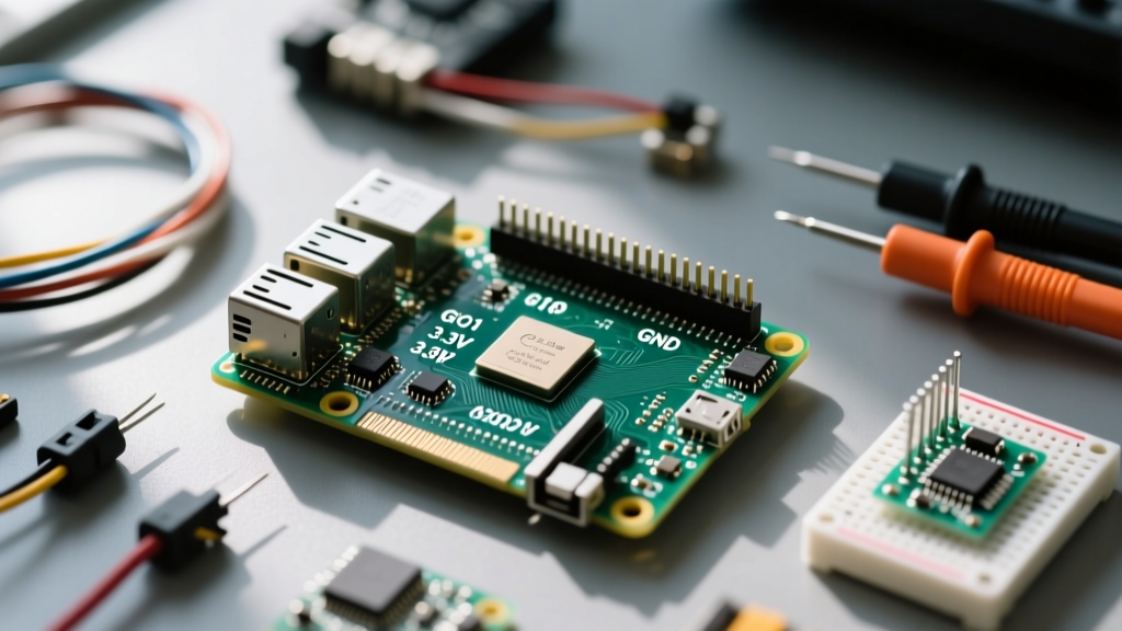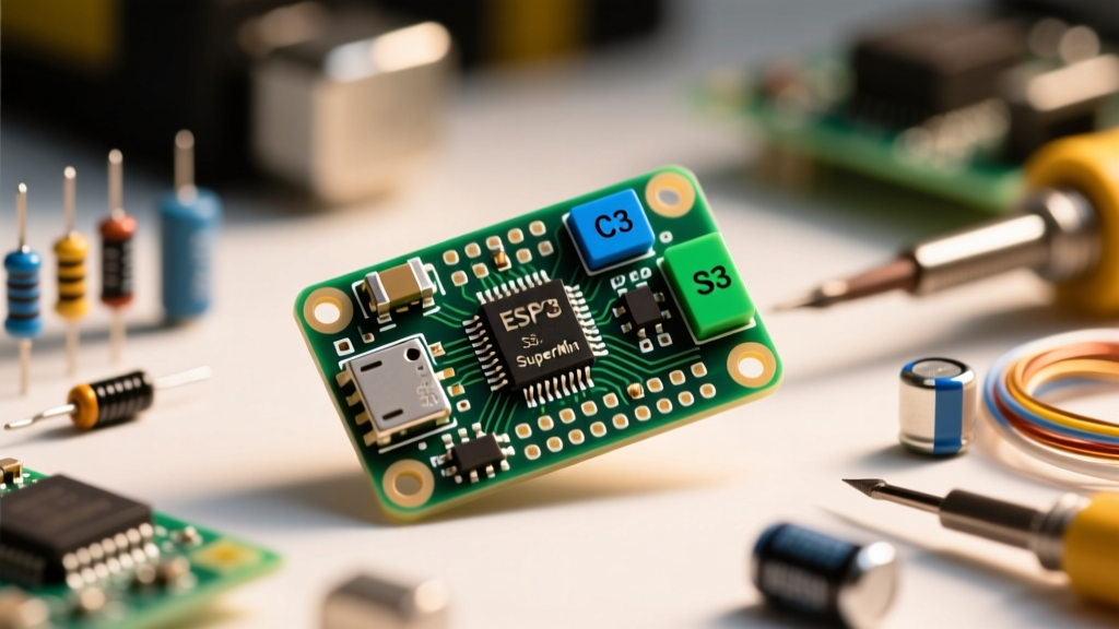

The maker community is constantly shrinking. Where the NodeMCU and standard ESP32 DevKit V1 once dominated workbenches with their sprawling 38-pin footprints, a new ultra-compact standard has emerged: the ESP32 SuperMini. Rather than a single official development board from Espressif, the 'SuperMini' moniker refers to a community-driven, ultra-dense breakout board form factor that has flooded the market via Asian semiconductor distributors. These boards strip away bulky USB-A converters and massive voltage regulators, offering a raw, surface-mount-friendly footprint that bridges the gap between prototyping and final PCB integration.
However, this radical reduction in size introduces unique hardware quirks, thermal limitations, and strapping pin traps that catch many Arduino developers off guard. In this concept explainer, we dissect the architecture, pinout realities, and practical implementation strategies for the ESP32 SuperMini ecosystem.
The Anatomy of the ESP32 SuperMini: C3 vs. S3
When sourcing an ESP32 SuperMini, you are generally choosing between two distinct silicon architectures. Understanding the difference is critical for firmware compatibility and peripheral selection.
- ESP32-C3 SuperMini: Powered by a single-core 32-bit RISC-V processor running at 160 MHz. It supports Wi-Fi 4 and Bluetooth 5 (LE). It is the most common and affordable 'SuperMini' variant, designed for low-cost IoT nodes where massive computational overhead is unnecessary.
- ESP32-S3 SuperMini: Features a dual-core Xtensa LX7 processor at 240 MHz, complete with vector instructions for AI acceleration, native USB OTG, and support for external PSRAM. It is physically slightly larger than the C3 but still adheres to the compact 'SuperMini' breadboard-friendly ethos.
Both variants abandon the traditional CP2102 or CH340 USB-to-UART bridge chips found on older DevKits. Instead, they utilize the chip's native USB interface (USB Serial/JTAG on the C3, and native USB OTG on the S3) directly routed to a USB-C receptacle. This eliminates a major point of failure and reduces the board's BOM cost and physical footprint.
Why the Form Factor Changes PCB Integration
The standard ESP32 DevKit measures roughly 55mm x 28mm. The ESP32 SuperMini shrinks this to an astonishing 22mm x 18mm (C3 variant). This is not just a novelty; it fundamentally changes how electrical engineers approach DIY-to-production pipelines.
By utilizing a 2.54mm pitched dual-inline package (DIP) layout, the SuperMini can be soldered directly into a custom motherboard using standard pin headers, acting as a surface-mount module without requiring the complex RF routing and impedance matching required when designing with raw ESP32-WROOM or ESP32-C3-MINI-1 modules.
The castellated or through-hole edge pins allow developers to prototype on a breadboard, then write the Arduino sketch, and finally solder the exact same board into a custom carrier PCB for a final product enclosure.
The Pinout Reality: Hidden GPIOs and Strapping Pin Traps
The most notorious aspect of the ESP32 SuperMini is its deceptive pinout. To maintain the 18-pin DIP footprint, several GPIOs are hidden, and the strapping pins are tightly coupled to onboard peripherals.
Navigating the Bootloader Matrix
Because the SuperMini lacks a dedicated auto-reset circuit (the DTR/RTS transistor matrix found on larger DevKits), developers frequently encounter the 'Failed to connect to ESP32: Timed out waiting for packet header' error in the Arduino IDE.
To manually force the board into the UART bootloader, you must manipulate the strapping pins during the reset sequence:
- Press and hold the BOOT button (which pulls GPIO9 to GND).
- Press and release the RST button while still holding BOOT.
- Release the BOOT button.
- Trigger the upload in the Arduino IDE.
Furthermore, GPIO8 on the C3 SuperMini is tied to an onboard WS2812 RGB LED. Because GPIO8 is a strapping pin that dictates SPI flash voltage and boot mode, driving this LED high/low during the exact millisecond of a hard reset can cause the chip to boot into an undefined state or fail to mount the filesystem. For production firmware, initialize GPIO8 only after the boot sequence has stabilized.
Power Profiling: Deep Sleep and Thermal Limits
The SuperMini is heavily marketed for battery-powered, deep-sleep applications. However, the onboard Low Dropout Regulator (LDO) dictates your power budget. Most clones use a generic ME6211 or similar SOT-23-5 LDO rated for 500mA, but the thermal dissipation on a 18x22mm PCB is virtually non-existent.
| Power State | ESP32-C3 SuperMini | ESP32-S3 SuperMini | Notes & Constraints |
|---|---|---|---|
| Active (WiFi TX Peak) | ~130 mA | ~240 mA | LDO may thermal-throttle if powered at 5V via USB-C during continuous TX. |
| Modem Sleep | ~20 mA | ~45 mA | WiFi connected, CPU paused. Safe for continuous 5V LDO operation. |
| Light Sleep | ~0.4 mA | ~0.8 mA | RAM retained, peripherals gated. Excellent for coin-cell backups. |
| Deep Sleep | ~5 µA | ~10 µA | Only RTC memory active. Bypass the onboard LDO and feed 3.3V directly to the 3V3 pin to eliminate LDO quiescent current. |
Pro-Tip for Battery Nodes: If you are designing a LiPo-powered node, do not route the battery through the SuperMini's 5V pin. The LDO will drain your battery via quiescent current. Instead, use an external ultra-low Iq regulator (like the HT7333) and feed regulated 3.3V directly into the 3V3 pin, bypassing the onboard circuitry entirely.
Arduino IDE Configuration for SuperMini Boards
Getting the Arduino IDE to recognize the native USB-JTAG interface of the SuperMini requires specific board manager configurations. According to the official Arduino ESP32 Core repository, native USB routing requires enabling CDC on boot.
- Open Board Manager and install the latest
esp32package by Espressif Systems (version 2.0.14 or higher recommended). - Select Tools > Board > ESP32 Arduino > ESP32C3 Dev Module (or S3 equivalent).
- Set USB CDC On Boot to Enabled. This routes
Serial.print()over the USB-C cable instead of the hardware UART pins. - Set Flash Mode to QIO and Partition Scheme to your required OTA/Spiffs layout.
If your board uses the CH340 serial chip instead of native USB (some early S3 SuperMini clones did this to ensure compatibility with older OS environments), you must select the standard ESP32 Dev Module and install the CH340 drivers.
Common Failure Modes and Hardware Debugging
When integrating the ESP32 SuperMini into permanent installations, electrical engineers must account for three primary failure modes unique to this compact form factor:
1. Antenna Detuning via Ground Plane Proximity
The PCB trace antenna on the SuperMini extends to the very edge of the board. The Espressif Hardware Design Guidelines explicitly state that no copper ground plane or metal enclosure should exist within 10mm of the antenna zone. Soldering the SuperMini flush against a massive ground plane on a custom carrier board will detune the impedance, dropping Wi-Fi range from 50 meters to under 3 meters.
2. The USB-C 'Charge-Only' Cable Trap
Because the SuperMini relies on native USB data lines (D+ and D-) directly connected to the SoC, using a cheap USB-C cable that lacks data wires will result in the board powering on, but the Arduino IDE will never detect a COM port. Always verify your cable with a known-good smartphone before blaming the board's USB controller.
3. GPIO Voltage Limitations
Unlike the original ESP32 which was somewhat tolerant of 5V logic on input pins (though technically out of spec), the ESP32-C3 and S3 are strictly 3.3V logic devices. Feeding a 5V I2C sensor signal into GPIO4 on a SuperMini will permanently degrade the silicon's ESD protection diodes, leading to high leakage currents that prevent the chip from entering Deep Sleep. Always use a bidirectional logic level shifter (like the BSS138) when interfacing with legacy 5V Arduino shields.
Summary
The ESP32 SuperMini represents a maturation in the DIY electronics space, offering professional-grade silicon in a footprint that respects the constraints of modern wearable and embedded IoT design. By respecting the thermal limits of the onboard LDO, carefully managing the GPIO8 and GPIO9 strapping pins, and properly configuring the native USB CDC stack in the Arduino IDE, developers can leverage these ultra-compact boards to transition seamlessly from breadboard prototype to production-ready hardware.