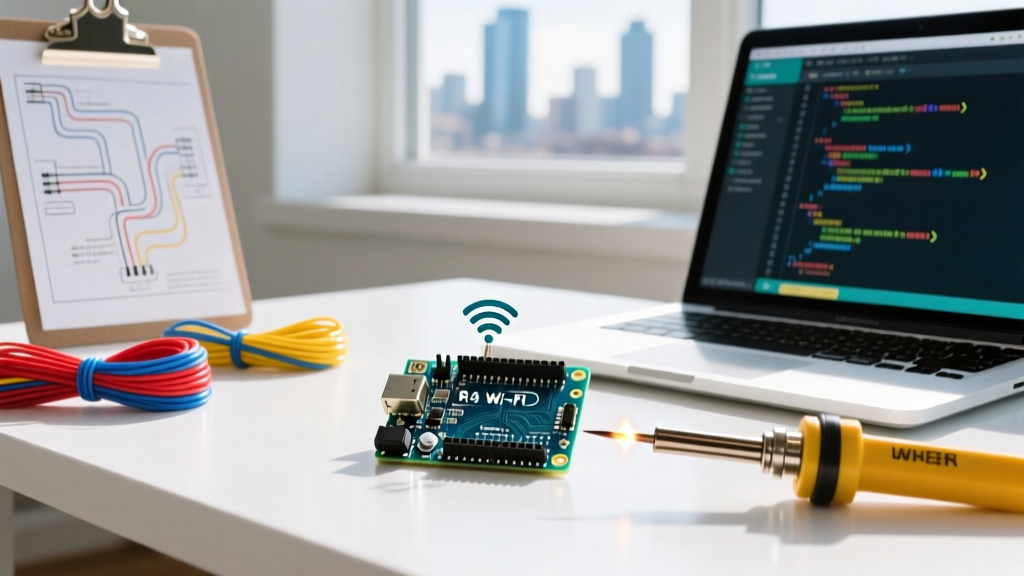

Demystifying the Platform: ¿Que Es Arduino?
If you have ever found yourself typing que es arduino into a search engine, you are standing at the gateway to the embedded systems revolution. At its core, Arduino is an open-source electronics platform based on easy-to-use hardware and software. However, from an engineering perspective, it is a robust ecosystem comprising a microcontroller unit (MCU) development board, a C++ integrated development environment (IDE), and a massive repository of community-driven libraries.
While legacy models relied on 8-bit AVR architecture, the modern 2026 landscape has shifted. Today's standard-bearer is the Arduino Uno R4 Wi-Fi, which leverages a 32-bit Renesas RA4M1 Arm Cortex-M33 processor paired with an ESP32-S3 for wireless connectivity. This tutorial will bypass the fluff and walk you through the exact hardware architecture, circuit calculations, and software configuration required to deploy your first microcontroller sketch.
Hardware Architecture: Choosing Your 2026 Board
Before writing code, you must understand the silicon you are commanding. The Arduino ecosystem offers various form factors, but selecting the right board dictates your project's ceiling. Below is a technical comparison of the three most relevant boards for makers and engineers today.
| Board Model | Primary MCU | Clock Speed | SRAM / Flash | Connectivity | Approx. Price (2026) |
|---|---|---|---|---|---|
| Uno R3 (Legacy) | ATmega328P (8-bit AVR) | 16 MHz | 2 KB / 32 KB | None | $24.00 |
| Uno R4 Wi-Fi | Renesas RA4M1 (32-bit Arm) | 48 MHz | 32 KB / 256 KB | Wi-Fi / BLE (ESP32-S3) | $27.50 |
| Nano ESP32 | ESP32-S3 (Dual-core Xtensa) | 240 MHz | 512 KB / 8 MB | Wi-Fi / BLE | $21.00 |
For this tutorial, we will use the Arduino Uno R4 Wi-Fi. Its 12-bit DAC, 16-bit PWM, and native HID capabilities make it vastly superior to the legacy R3 for modern sensor integration and IoT prototyping. For deeper architectural specifications, you can review the Renesas RA4M1 official datasheet.
Step 1: IDE Configuration and Toolchain Setup
The Arduino IDE translates your C++ code into machine-level hex files and flashes them via a serial bootloader.
- Download the IDE: Install Arduino IDE 2.3.x from the Arduino Official Documentation hub. The 2.x branch includes modern features like auto-completion and real-time serial plotting.
- Install the Board Core: Open the IDE, navigate to Tools > Board > Boards Manager, and search for
Arduino UNO R4 Boards. Install the latest Renesas core package. - Driver Verification: The Uno R4 uses a native USB-C interface. Unlike older boards that required CH340 or FTDI drivers, the R4 enumerates as a standard CDC-ACM device on Windows, macOS, and Linux. Ensure your USB-C cable is rated for data transfer, not just power delivery.
Step 2: Circuit Wiring and Ohm's Law Calculation
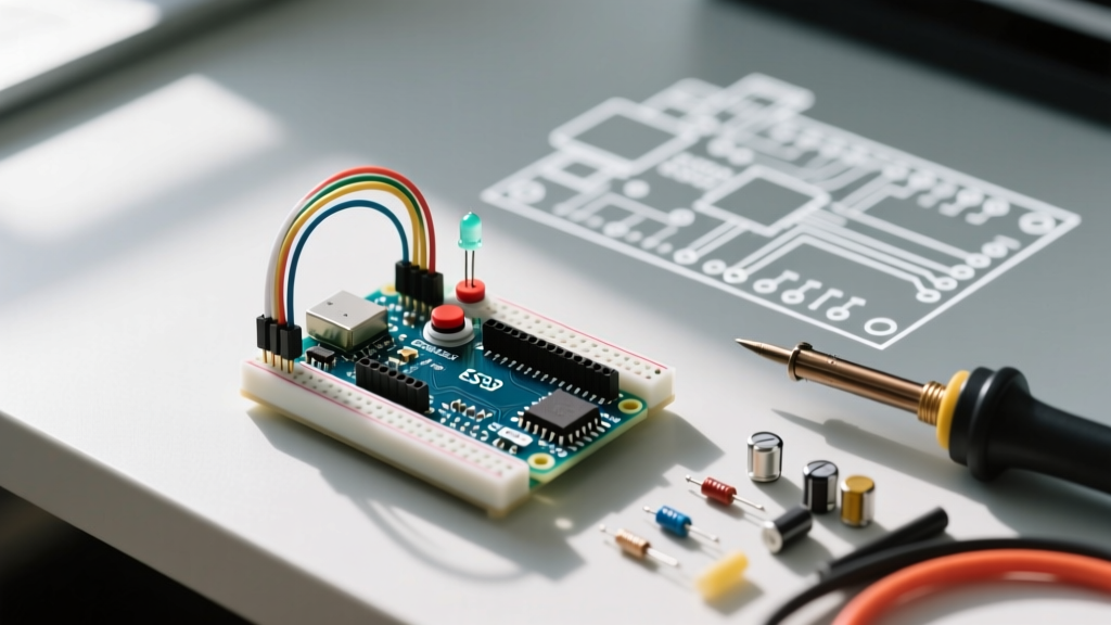
We will build an external LED circuit. While the board features an onboard LED tied to GPIO Pin 13, building an external circuit teaches fundamental current-limiting principles.
Calculating the Current-Limiting Resistor
Connecting an LED directly to a 5V GPIO pin will cause catastrophic thermal runaway, destroying the LED and potentially damaging the MCU's GPIO bank. We must use Ohm's Law to calculate the required resistance.
Formula: R = (V_source - V_forward) / I_desired
- V_source: 5.0V (Uno R4 GPIO output)
- V_forward: ~2.0V (Standard 5mm Red LED)
- I_desired: 15mA (0.015A) for optimal brightness without exceeding the 20mA absolute maximum rating.
Calculation: R = (5.0 - 2.0) / 0.015 = 200Ω.
The closest standard E12 series resistor is 220Ω (Color bands: Red-Red-Brown-Gold). For a comprehensive breakdown of circuit physics, refer to the SparkFun Ohm's Law Tutorial.
Physical Wiring Steps
- Insert the 220Ω resistor into the breadboard. Connect one leg to GPIO Pin 8 on the Uno R4 using a male-to-male jumper wire.
- Connect the other leg of the resistor to the Anode (longer leg) of the 5mm LED.
- Connect the Cathode (shorter leg, flat edge) of the LED to the breadboard's ground rail.
- Run a jumper wire from the breadboard's ground rail to the GND pin on the Arduino.
Step 3: Writing the C++ Sketch
Arduino code, known as a 'sketch', relies on two primary functions: setup() which runs once upon boot, and loop() which executes continuously. Below is the optimized C++ code to pulse our external LED.
// Define the GPIO pin constant
const int LED_PIN = 8;

void setup() {
  // Initialize the digital pin as an output
  pinMode(LED_PIN, OUTPUT);

  // Initialize Serial Monitor for debugging
  Serial.begin(115200);
  Serial.println("System Initialized: LED Control Active");
}

void loop() {
  digitalWrite(LED_PIN, HIGH);  // Drive pin to 5V (Source current)
  delay(500);                   // Non-blocking pause (500ms)

  digitalWrite(LED_PIN, LOW);   // Drive pin to 0V (Sink current)
  delay(500);

  Serial.println("Blink cycle complete");
}
Code Architecture Notes
Notice the use of const int instead of #define for pin mapping. In modern C++ compilation via GCC (which the Arduino IDE uses under the hood), const respects variable scoping rules and provides better type safety during the compilation phase. Furthermore, initializing the Serial Monitor at 115200 baud allows for high-speed telemetry debugging without bottlenecking the MCU's main execution loop.
Step 4: Compilation, Upload, and Troubleshooting
Click the Upload button (right-pointing arrow) in the IDE. The IDE will compile the sketch, invoke the bossac or avrdude uploader tool, and transfer the binary via the USB-C connection.
Common Failure Modes and Edge Cases
If your upload fails, do not panic. Embedded development requires systematic debugging. Here are the most common 2026 failure modes:
- Error:
avrdude: stk500_getsync() attempt 1 of 10: not in sync: resp=0x00
Diagnosis: The IDE is communicating with the wrong COM port, or a charge-only USB cable is connected.
Fix: Navigate to Tools > Port and select the port explicitly labeled 'Arduino Uno R4'. Swap your USB-C cable for a verified data-sync cable. - Error:
Compilation Error: 'LED_PIN' was not declared in this scope
Diagnosis: A typographical error or case-sensitivity issue in the C++ syntax. C++ is strictly case-sensitive.
Fix: Ensure variable declarations match their usage exactly. - Hardware Issue: LED is extremely dim or flickering.
Diagnosis: Breadboard contact resistance or incorrect resistor value.
Fix: Use a multimeter to verify the resistor reads ~220Ω. Ensure jumper wires are fully seated in the breadboard's spring clips.
Scaling Beyond the Blink: Next Steps
Understanding que es arduino is only the first step. Once you have mastered GPIO manipulation and basic circuit theory, the platform scales into advanced domains. The Uno R4's integrated ESP32-S3 module allows you to transition from simple blink sketches to MQTT-based IoT sensor nodes, connecting to AWS IoT Core or local Home Assistant servers via Wi-Fi.
Your immediate next step should be exploring Pulse Width Modulation (PWM) using the analogWrite() function to fade the LED, and subsequently integrating an I2C environmental sensor like the BME280 to log temperature and humidity data directly to an SD card or cloud dashboard.