
The ESP32 System on Chip (SoC) ecosystem has evolved dramatically since the original dual-core Xtensa LX6 chip launched. Today, Espressif offers a diverse lineup of microcontrollers featuring RISC-V architectures, AI vector instructions, and varying wireless protocols. For hardware engineers and DIY makers, navigating this Espressif SoC lineup requires more than just picking a board; it demands a deep understanding of SoC-specific configuration, partition schemes, and hardware strapping pins to ensure stable operation.
Decoding the ESP32 SoC Family Tree
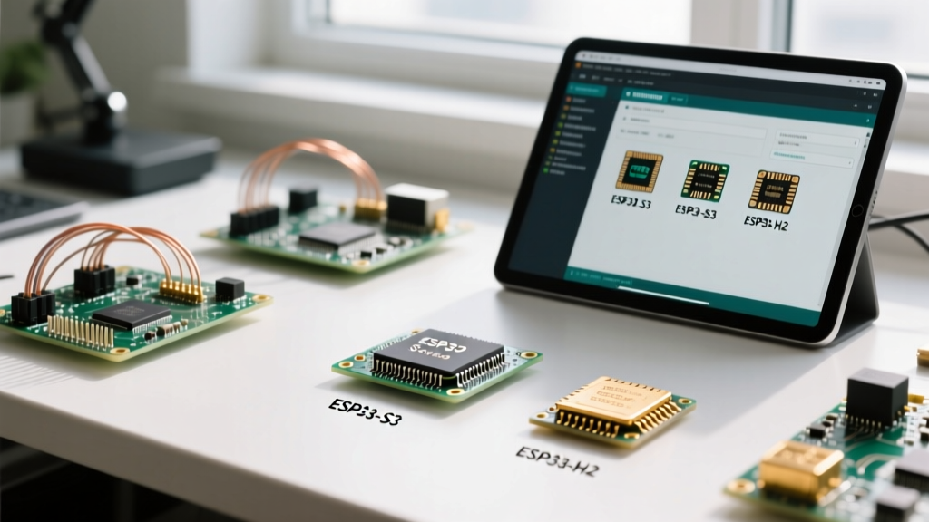
Before configuring your IDE, you must select the right silicon for your application. The modern ESP32 family is split between the legacy Xtensa architecture and the newer, highly efficient RISC-V cores. Choosing incorrectly can lead to severe bottlenecks in power consumption or wireless range.
| SoC Model | Architecture | Cores / Clock | Wireless Capabilities | Special Features | Approx. Price |
|---|---|---|---|---|---|
| ESP32 (Original) | Xtensa LX6 | Dual / 240MHz | Wi-Fi 4, BLE 4.2 | Capacitive Touch, Hall Sensor | $2.50 |
| ESP32-S3 | Xtensa LX7 | Dual / 240MHz | Wi-Fi 4, BLE 5.0 | Vector AI Instructions, Native USB | $2.80 |
| ESP32-C3 | RISC-V | Single / 160MHz | Wi-Fi 4, BLE 5.0 | Pin-compatible with ESP8266, Native USB | $1.20 |
| ESP32-C6 | RISC-V | Single / 160MHz | Wi-Fi 6, BLE 5, 802.15.4 | Thread/Zigbee Matter Support | $1.60 |
| ESP32-H2 | RISC-V | Single / 96MHz | BLE 5, 802.15.4 (No Wi-Fi) | Ultra-low power Matter/Zigbee | $1.10 |
Expert Insight: If your project requires local AI inference (like wake-word detection or basic image classification), the ESP32-S3 is mandatory due to its 128-bit SIMD vector acceleration. For simple IoT sensors, the ESP32-C3 offers a vastly superior price-to-performance ratio and lower deep-sleep current.
Arduino IDE Core Configuration and Board Selection
To program these variants, you must install the official Arduino ESP32 Core via the Boards Manager. Once installed, the 'Tools' menu presents a labyrinth of configuration options that directly dictate how the ESP32 SoC compiles and boots.
The Partition Scheme Trap
The most common point of failure for intermediate makers is the Partition Scheme. By default, the Arduino IDE selects 'Default 4MB with spiffs (1.2MB APP, 1.5MB SPIFFS)'. This is a dangerous default for any project utilizing Over-The-Air (OTA) updates.
- Default Scheme: Allocates 1.25MB for the application. If your compiled sketch exceeds 1.25MB (easily done when adding large libraries like TensorFlow Lite or LVGL), the upload will fail or corrupt the bootloader.
- OTA Requirement: OTA updates require two identical application partitions (one running, one receiving the new firmware). Therefore, on a 4MB flash chip, the maximum app size is roughly 1.9MB.
- The Fix: Always select 'Minimal SPIFFS (1.9MB APP, 190KB SPIFFS)' or 'Huge APP (3MB No OTA/Spiffs)' if you are not using OTA but have a massive codebase.
Navigating USB CDC and Serial Routing
With the introduction of the ESP32-S3 and ESP32-C3, Espressif integrated native USB directly into the SoC, eliminating the need for external UART-to-USB bridge chips like the CP2102 or CH340 on many modern dev boards. However, this introduces a massive configuration hurdle: Serial routing.
If you are using a board with native USB and you cannot see Serial.print() output in the Arduino IDE Serial Monitor, you have likely misconfigured the USB CDC settings. In the Arduino IDE 'Tools' menu, you must set USB CDC On Boot to Enabled. This routes the standard Serial object to the native USB peripheral. If left disabled, the SoC routes serial data to hardware UART0, which is physically disconnected from the USB data lines on native-USB-only boards.
Flash Mode and Frequency Tuning
Under the 'Tools' menu, you will also find 'Flash Mode' and 'Flash Frequency'. While 'QIO 80MHz' is the default and provides the fastest read speeds for XIP (Execute In Place), some cheaper clone boards with substandard SPI flash chips will fail to boot at 80MHz. If you encounter a continuous boot-loop with the error flash read err, 1000, drop the Flash Mode to DIO and the frequency to 40MHz to stabilize the SPI bus.
Hardware Strapping Pins and Boot Failures
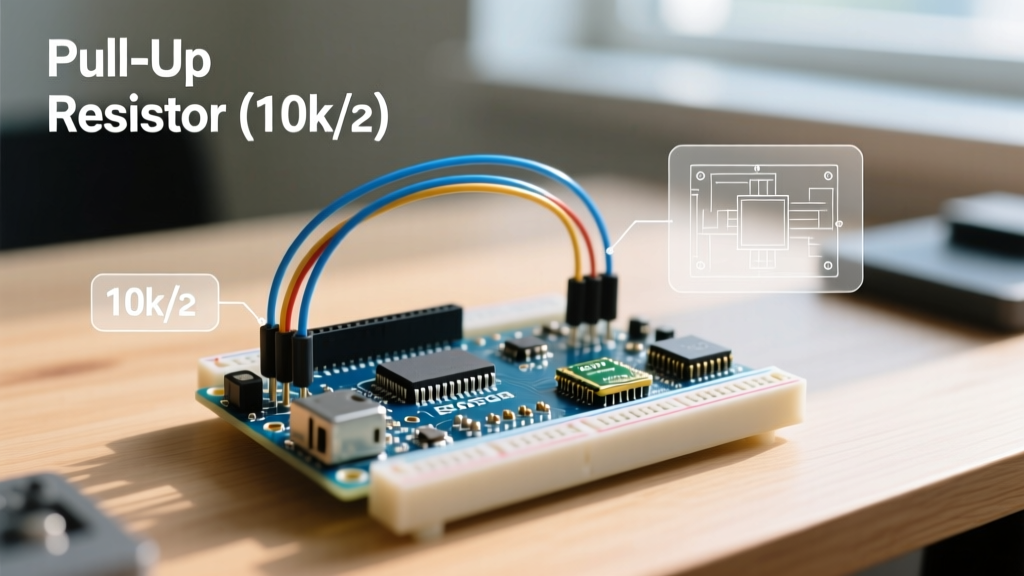
Every ESP32 SoC variant utilizes specific GPIOs as 'strapping pins' to determine the boot mode during power-on reset. If these pins are pulled to the wrong logic level by external sensors or relays, the SoC will enter the serial bootloader or fail to boot entirely.
Original ESP32 Strapping Pins
- GPIO 0: Must be HIGH for normal SPI flash boot. If pulled LOW, it enters UART download mode.
- GPIO 2: Must be LOW or floating. If pulled HIGH, the SoC attempts to boot from the SDIO interface, resulting in a boot failure.
- GPIO 12 (MTDI): Dictates the flash voltage. If pulled HIGH, it expects 1.8V flash; if LOW, 3.3V. Incorrectly pulling this HIGH on a 3.3V board will brick the boot process.
- GPIO 15 (MTDO): Controls SDIO timing and boot log output.
ESP32-S3 Strapping Pins
The S3 variant shifts these critical pins. GPIO 3, GPIO 45, and GPIO 46 dictate SPI boot mode, SPI voltage, and boot log printing. Always consult the official Espressif Hardware Design Guidelines before wiring relays or pull-down resistors to these specific GPIOs.
Power Supply Decoupling for RF Stability
A properly configured ESP32 SoC in software will still fail if the hardware power delivery is inadequate. When the Wi-Fi or Bluetooth radio transmits, the SoC can draw current spikes exceeding 500mA for brief microseconds. Many budget development boards utilize cheap 3.3V LDOs (like the AMS1117) that cannot respond quickly enough to these transient spikes, triggering the SoC's internal Brownout Detector (BOD).
When the BOD triggers, the ESP32 instantly resets, often printing Brownout detector was triggered to the serial monitor right as it attempts to connect to a Wi-Fi router. To resolve this:
- Add a 100µF tantalum or low-ESR electrolytic capacitor directly across the 3.3V and GND pins on your custom PCB.
- Place a 100nF ceramic decoupling capacitor as close to the SoC's VDD pins as physically possible.
- In the Arduino IDE, use
WiFi.setTxPower(WIFI_POWER_8_5dBm);to artificially limit the RF transmission power, thereby reducing the peak current draw if your power supply is constrained.
When to Abandon Arduino for ESP-IDF
While the Arduino IDE is excellent for rapid prototyping, it abstracts away the FreeRTOS task management and deep power states. If your ESP32 SoC configuration requires microamp-level deep sleep currents, custom MAC layer tuning, or secure boot encryption, you must transition to the native ESP-IDF framework. The ESP-IDF's menuconfig utility allows you to disable unused peripherals (like the ADC or I2C controllers) at the silicon level, shaving crucial milliamps off your active current budget—a level of configuration the Arduino core simply does not expose.