
The Core Misconception: PWM vs. True Analog Voltage
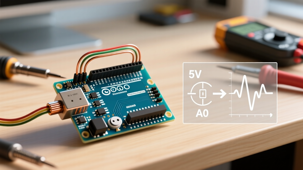
One of the most frequent hurdles for makers and embedded engineers is the realization that the analogWrite() function on standard Arduino boards does not output a true analog voltage. When you execute analogWrite(pin, 127) on an Arduino Uno R3, you are not getting a steady 2.5V DC signal. Instead, the ATmega328P microcontroller generates a 5V square wave with a 50% duty cycle, rapidly switching between 0V and 5V. According to the official Arduino analogWrite() reference, this Pulse Width Modulation (PWM) simulates analog behavior for components with high inertia (like LEDs or DC motors), but it fails catastrophically for precision analog circuits, audio generation, or direct sensor biasing.
If your circuit is behaving erratically, your multimeter is showing confusing readings, or your audio output sounds like a harsh buzz, you are likely encountering the hardware limitations of PWM. This guide provides deep-level troubleshooting and hardware fixes to resolve your Arduino analog write issues.
Troubleshooting Matrix: Why Your Analog Write is Failing
Before redesigning your circuit, identify the exact failure mode using the diagnostic matrix below.
| Symptom | Root Cause | Hardware/Software Fix |
|---|---|---|
| Output is stuck at 0V or 5V (No fading) | Using a non-PWM digital pin | Move wire to a pin marked with a tilde (~) |
| PWM stops working when Servo is attached | Timer1 hardware conflict | Move PWM to pins 3, 5, 6, or 11 |
| Multimeter reads 2.5V, but op-amp saturates | Meter averages PWM; op-amp sees 5V peaks | Add an RC low-pass filter |
| Audio output has a high-pitched whine | PWM carrier frequency (490Hz) is in audio band | Alter Timer registers or use a true DAC |
| Output voltage sags under load | Exceeding ATmega328P 20mA pin limit | Use a logic-level MOSFET or op-amp buffer |
Timer Conflicts: The Silent PWM Killer
The ATmega328P relies on internal hardware timers to generate PWM signals. When you include certain libraries in your sketch, they hijack these timers, silently disabling analogWrite() on specific pins.
The Servo Library Trap
The standard Servo.h library requires a high-precision 16-bit timer to generate the 50Hz pulse train required by hobby servos. On the Arduino Uno, it claims Timer1. Consequently, calling myservo.attach(9) instantly disables PWM on pins 9 and 10. If your LED or motor is connected to pin 9, it will simply stop working or lock at its last state.
The Tone() Function Conflict
Using the tone() function to drive a piezo buzzer hijacks Timer2. This immediately kills PWM functionality on pins 3 and 11. As detailed in SparkFun's Pulse Width Modulation Tutorial, understanding timer mapping is non-negotiable for complex sketches.
ATmega328P Timer-to-Pin Mapping
- Timer0 (980 Hz): Pins 5, 6 (Note: Altering Timer0 breaks
delay()andmillis()). - Timer1 (490 Hz): Pins 9, 10 (Hijacked by
Servo.h). - Timer2 (490 Hz): Pins 3, 11 (Hijacked by
tone()).
Hardware Fixes: Designing an RC Low-Pass Filter
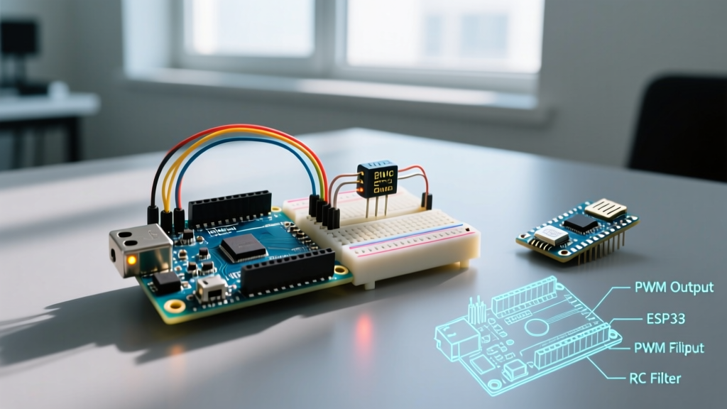
If your application requires a true DC voltage—such as providing a programmable reference voltage to an op-amp comparator or generating a basic DC bias—you must convert the PWM square wave into a smooth DC line using a passive RC (Resistor-Capacitor) low-pass filter.
Design Rule of Thumb: The cutoff frequency ($f_c$) of your RC filter should be at least 10 times lower than the PWM frequency to minimize voltage ripple. For standard Arduino pins running at 490 Hz, target an $f_c$ of roughly 40 Hz or lower.
Recommended Component Values for 490 Hz PWM:
- Resistor (R): 10 kΩ (Limits current draw from the microcontroller pin).
- Capacitor (C): 1 µF (Yields $f_c \approx 15.9$ Hz).
- Capacitor Dielectric Warning: Avoid cheap Y5V ceramic capacitors for precision analog filtering. Their capacitance drops drastically under DC bias voltage. Use C0G/NP0 ceramics or polyester film capacitors to maintain linearity across the 0-5V range.
Trade-off: A 10kΩ/1µF filter provides a very smooth DC voltage, but the step response is slow. If you change the analogWrite() value from 0 to 255, it will take approximately 35 milliseconds ($5 \times RC$) to settle at the new voltage. This is unacceptable for audio or fast-acting control loops.
Upgrade Path: When to Ditch PWM for a True DAC
If you are building an audio synthesizer, a precision programmable power supply, or a function generator, passive filtering will eventually bottleneck your project. Upgrading to a Digital-to-Analog Converter (DAC) is the professional solution.
1. The I2C DAC: MCP4725 (Best for Arduino Uno/Nano)
The Microchip MCP4725 is a 12-bit DAC that communicates over I2C. It outputs a true, ripple-free analog voltage instantly. In 2026, breakout boards from Adafruit or SparkFun typically retail between $9.00 and $12.00. Because it uses I2C (pins A4/A5 on Uno), it leaves all your hardware timers and PWM pins completely free.
Code Implementation:
#include <Adafruit_MCP4725.h>
Adafruit_MCP4725 dac;
void setup() {
  dac.begin(0x62);
}
void loop() {
  // Outputs true 2.5V (assuming 5V VDD)
  dac.setVoltage(2048, false);
}
2. The ESP32 Internal DAC (Proceed with Caution)
The original ESP32 chip features two internal 8-bit DACs mapped to GPIO25 and GPIO26. You can use dacWrite(25, 128) to output roughly 1.65V. However, a massive trap for modern makers is the silicon revision: the wildly popular ESP32-S3 and ESP32-C3 variants do not include internal DACs. If you design a PCB assuming an internal DAC and later switch to an ESP32-S3 for better AI/USB support, your analog output will fail entirely.
3. High-Resolution SPI DACs: AD5693
For industrial-grade 16-bit precision (e.g., calibrating lab equipment), the Analog Devices AD5693 via SPI provides microvolt-level resolution, though it requires a dedicated external voltage reference (like the REF3033) to achieve its full datasheet accuracy.
Advanced Debugging: Measuring the Signal
Do not trust a standard $15 digital multimeter when debugging analogWrite(). Multimeters sample at a few Hz and mathematically average the incoming voltage. If you measure a 50% duty cycle 5V PWM wave, the multimeter will display ~2.5V, tricking you into thinking you have a true analog signal. To properly debug, you must use an oscilloscope (even a $50 USB logic analyzer/DSO like the DSO138 or a Rigol DS1054Z). Look for the square wave edges and measure the peak-to-peak voltage to confirm PWM behavior.
Frequently Asked Questions
Can I change the PWM frequency of analogWrite()?
Yes, but it requires direct register manipulation. By altering the prescaler bits in the TCCR1B register, you can push Timer1's PWM frequency up to 31.25 kHz, which moves the carrier noise far above the human hearing range for audio projects. Consult the Microchip ATmega328P Datasheet for exact bit-shifting syntax.
Why does my LED flicker at low analogWrite values?
The human eye has a logarithmic response to light. The jump from analogWrite(pin, 0) to analogWrite(pin, 1) represents a massive perceived brightness leap, while 254 to 255 is imperceptible. To fix this, do not use linear values; apply a gamma-correction lookup table in your code to map linear inputs to perceptual PWM outputs.
Does the Arduino Due output true analog voltage?
Yes. Unlike the AVR-based Uno, the Arduino Due (SAM3X8E ARM Cortex-M3) features two true 12-bit DAC pins (DAC0 and DAC1). Using analogWrite(DAC0, 2048) on a Due outputs a genuine, steady 1.65V DC signal without requiring external hardware.