
Diagnosing Arduino Diode Failures: A Multimeter-First Approach
When an Arduino project behaves erratically—resetting randomly, failing to boot, or producing noisy sensor data—makers often blame the microcontroller or the code. However, as of 2026, passive component mismanagement remains one of the leading causes of field failures in DIY and prototyped embedded systems. Specifically, the humble Arduino diode circuit is frequently misunderstood, leading to catastrophic inductive kickback, silent voltage drop brownouts, and signal integrity degradation.
Before swapping out your ATmega328P or rewriting your sketch, you must verify your diode network. Set your digital multimeter (DMM) to the Diode Test Mode (usually indicated by a diode symbol). According to the All About Circuits semiconductor textbook, a healthy silicon diode will display a forward voltage ($V_f$) between 0.500V and 0.700V, while a Schottky diode will read between 0.200V and 0.400V. Reversing the probes should yield an 'OL' (Open Loop) reading. If you see 0.000V in both directions, the diode is shorted; if you see 'OL' in both directions, the internal junction is blown open.
Scenario 1: Inductive Kickback and the Missing Flyback Diode
The most notorious Arduino diode issue occurs when switching inductive loads like relays, solenoids, or DC motors. When you use a transistor (such as a TIP120 or 2N2222) to turn off a 5V Songle SRD-05VDC-SL-C relay, the magnetic field in the relay coil collapses. According to Faraday's Law of Induction ($V = -L \frac{di}{dt}$), this rapid change in current generates a massive reverse voltage spike. A standard 70mH relay coil switching off in 1 microsecond can generate a negative spike exceeding -100V.
This spike couples into the Arduino's ground plane, causing a phenomenon known as 'ground bounce.' The ATmega328P interprets this transient noise as a clock glitch or a brownout, resulting in an immediate, unexplained reset.
The Fix: Proper Flyback Diode Selection and Placement
To clamp this spike, you must place a flyback (freewheeling) diode in parallel with the inductive load, reverse-biased during normal operation (cathode to the positive supply, anode to the transistor drain/collector).
- The 1N4007 Standard: For low-frequency switching (under 1 kHz) like standard relays, the 1N4007 is the undisputed workhorse. With a Peak Inverse Voltage (PIV) of 1000V and a 1A continuous current rating, it easily absorbs the kickback. A 100-pack costs roughly $4.50 in 2026.
- The 1N4148 Signal Diode: Many beginners mistakenly use the 1N4148 for flyback protection. While it switches faster, its 100V PIV and 300mA continuous current rating are often insufficient for larger solenoids or high-current DC motors, leading to diode vaporization.
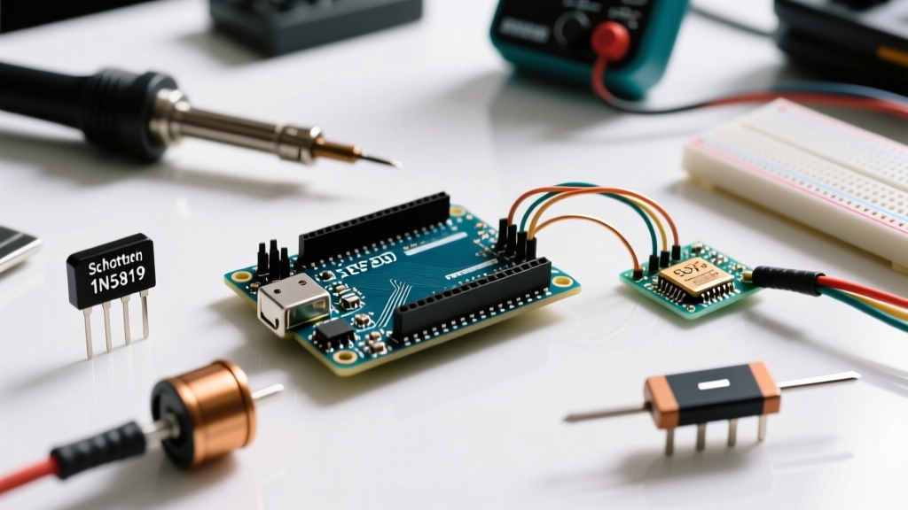
- Schottky for High-Frequency PWM: If you are driving a motor with 20 kHz PWM, the slow reverse recovery time ($t_{rr}$) of the 1N4007 (approx. 30µs) will cause it to overheat and fail. Use a fast-recovery diode like the UF4007 or a Schottky diode like the 1N5819 instead.
Pro Tip: Never place the flyback diode on the breadboard far away from the relay coil. The physical loop area between the coil and the diode acts as an antenna, radiating Electromagnetic Interference (EMI) that can still disrupt sensitive I2C or SPI buses. Solder the diode directly across the relay coil pins.
Scenario 2: Silicon Voltage Drops Triggering ATmega328P Brownouts
A frequent mistake in custom Arduino power supply design is using a standard silicon rectifier diode (like the 1N400x series) in series with the 5V rail for reverse polarity protection. While this prevents catastrophic damage if the battery is wired backward, it introduces a severe voltage drop.
Under a moderate load of 500mA (e.g., powering an Arduino Nano, a few sensors, and an SD card module), a 1N4007 will drop approximately 0.85V. If your USB power source is outputting a slightly sagging 4.8V, the voltage reaching the ATmega328P's VCC pin drops to 3.95V. According to the official Microchip ATmega328P product documentation, the default Brown-out Detection (BOD) threshold for 5V/16MHz configurations is typically set to 4.3V via fuse bits. When the voltage dips below 4.3V, the BOD circuitry forcefully holds the microcontroller in reset, causing the project to fail to boot or restart whenever a high-current peripheral (like a NeoPixel strip) activates.
Diode Forward Voltage ($V_f$) Comparison Matrix
| Diode Type / Model | Typical $V_f$ @ 500mA | Reverse Recovery / Speed | Best Arduino Application | Approx. Cost (per unit) |
|---|---|---|---|---|
| 1N4007 (Silicon Rectifier) | 0.85V - 1.10V | Slow (30µs) | AC Rectification, Low-Freq Flyback | $0.04 |
| 1N5819 (Schottky) | 0.30V - 0.45V | Instantaneous | Reverse Polarity Protection, Solar | $0.06 |
| SS34 (SMD Schottky) | 0.40V - 0.55V | Instantaneous | High-Current 3A Power Rails | $0.08 |
| 1N4148 (Silicon Signal) | 0.70V - 1.00V | Fast (4ns) | Logic Gate Steering, Signal Clamping | $0.02 |
The Fix: Upgrading to Schottky or Ideal Diode Controllers
To eliminate the brownout issue while maintaining reverse polarity protection, swap the 1N4007 for a 1N5819 Schottky diode. The lower $V_f$ (~0.35V) ensures your 5V rail stays well above the 4.3V BOD threshold. For high-current applications exceeding 1A where even a 0.4V drop generates excessive heat ($P = I \times V_f$), upgrade to an 'Ideal Diode' controller IC like the LTC4376, which drives an external N-channel MOSFET to achieve a voltage drop of less than 20mV.
Scenario 3: Signal Clamping and I2C Bus Capacitance
Makers often attempt to protect Arduino I2C pins (A4/A5 on the Uno) from 5V-to-3.3V logic level mismatches by placing standard 1N4148 diodes as clamps to the 3.3V rail. While this prevents the pin voltage from exceeding 3.3V + $V_f$, it introduces a hidden killer: Junction Capacitance ($C_j$).
Standard signal diodes possess a junction capacitance of roughly 4pF to 10pF. When reverse-biased on a high-speed I2C bus (e.g., 400 kHz Fast Mode), this capacitance combines with the I2C pull-up resistors (typically 4.7kΩ) to form a low-pass RC filter. This severely degrades the rise-time of the SDA and SCL lines, resulting in corrupted data packets and 'Device Not Found' errors. For logic clamping on communication buses, always use specialized low-capacitance TVS (Transient Voltage Suppression) diodes like the PESD5V0S1BA, which offer a capacitance of less than 1pF. For a deeper understanding of component parasitics, refer to SparkFun's comprehensive guide to diodes.
Master Troubleshooting Matrix for Arduino Diode Circuits
Use this diagnostic matrix to quickly isolate and resolve diode-related hardware faults in your MCU projects.
| Observed Symptom | Probable Diode Failure Mode | Multimeter / Scope Test | Corrective Action |
|---|---|---|---|
| Arduino resets exactly when a relay clicks off. | Missing, backward, or undersized flyback diode causing ground bounce. | Check for -10V+ spikes on the 5V rail using an oscilloscope. | Install 1N4007 across the relay coil (Cathode to 5V). |
| Project fails to boot; power LED is dim. | Excessive $V_f$ on series protection diode triggering BOD. | Measure voltage drop across the protection diode under load. | Replace Silicon diode with 1N5819 Schottky or P-FET. |
| I2C OLED display flickers or fails initialization. | High junction capacitance from clamp diodes ruining signal rise-time. | Scope the SDA line; look for sloped, rounded square waves. | Remove 1N4148 clamps; use proper logic level shifters. |
| Protection diode gets hot and emits a burning smell. | Diode rated for insufficient continuous forward current ($I_f$). | Measure total system current draw with DMM in series. | Upgrade to SS34 (3A) or use a P-Channel MOSFET crowbar. |
Summary: Designing Robust MCU Protection
Troubleshooting an Arduino diode network requires looking beyond simple continuity. You must account for transient recovery times, parasitic capacitance, and the strict Brown-out Detection thresholds of the ATmega328P. By selecting the exact diode chemistry (Silicon vs. Schottky vs. TVS) matched to your specific load profile, you can eliminate erratic resets and build embedded systems that survive real-world electrical abuse.