
The Deceptive Simplicity of the ESP32-C3 Super Mini
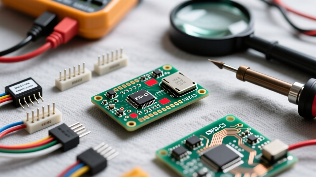
The ESP32-C3 Super Mini has taken the maker community by storm. Offering a RISC-V single-core 160MHz processor, Wi-Fi, and Bluetooth 5 in a footprint barely larger than a postage stamp, it is the ultimate drop-in replacement for the Arduino Pro Micro or Nano. However, its ultra-compact size forces severe hardware compromises. When you combine aggressive cost-cutting on clone manufacturing with a lack of standard auto-reset circuitry, the result is a minefield of hardware and wiring faults.
If you are staring at a "Timed out waiting for packet header" error, experiencing random brownout resets, or wondering why your I2C sensors are preventing the board from booting, you are likely a victim of the esp32-c3 super mini pinout quirks. This diagnostic guide bypasses the basic tutorials and dives straight into the silicon-level realities, schematic discrepancies, and boot-strap conflicts that plague this specific development board.
Critical Pinout Discrepancies: Silkscreen vs. Reality
The most frequent source of wiring errors stems from blind trust in the board's silkscreen. Because the ESP32-C3 Super Mini is produced by dozens of unregulated factories, the silkscreen labels often contradict the actual GPIO routing. Below is a diagnostic translation table for the most problematic pins.
| Silkscreen Label | GPIO Number | Hidden Error Trap / Actual Function |
|---|---|---|
| 5V | N/A | USB VBUS or external input. Feeds a low-cost ME6211 LDO. Do not backfeed 5V from a motor shield; the trace width and LDO reverse-polarity protection are often non-existent. |
| 3V3 | N/A | LDO Output. Max safe continuous draw is ~300mA before thermal shutdown triggers a brownout. |
| TX / RX | 21 / 20 | Hardware UART0. Frequently mislabeled as GPIO0/GPIO1 on early or ultra-cheap clone batches. Always verify with a multimeter continuity test to the main chip if UART fails. |
| D2 | 2 | Boot Strap Pin. Must be LOW on reset. Attaching I2C devices with pull-ups here will brick the boot sequence. |
| D8 | 8 | Boot Strap & Onboard LED. Shared with SPI Flash on some core variants; avoid using as a standard PWM output. |
| D9 | 9 | Boot Button. Pulling LOW forces UART Download Mode. Internally pulled HIGH. |
| D18 / D19 | 18 / 19 | Native USB D- / D+. Routed directly to the ESP32-C3 internal USB-Serial/JTAG controller. No external CP2102 or CH340 bridge chip is present. |
Diagnosing the "Timed Out" Flashing Error
The most universally reported error in the Arduino ESP32 Core GitHub Issues tracker for this board is the failure to enter download mode automatically. Unlike full-sized ESP32 dev boards, the Super Mini lacks the DTR/RTS transistor auto-reset circuit. The IDE cannot automatically pulse the EN (Reset) and GPIO9 (Boot) pins.
The Symptom: The Arduino IDE compiles successfully, but the console hangs on Connecting... and eventually throws a Timed out waiting for packet header fatal error.
The Hardware Fix: You must manually force the chip into UART Download Mode using the physical buttons on the board. Follow this exact sequence:
- Press and hold the BOOT button (GPIO9 to GND).
- While holding BOOT, press and release the RESET button (EN to GND).
- Release the BOOT button.
- Immediately click the "Upload" button in the Arduino IDE.
Pro-Tip: If your board lacks a physical RESET button (common on the absolute smallest variants), you can simulate a reset by briefly shorting the 3V3 pin to GND or using a wired momentary switch on the EN pin.
GPIO Boot Strap Conflicts: The Silent Boot Killer
The ESP32-C3 relies on the logic states of specific GPIO pins during the first few milliseconds of power-on to determine its boot source. According to the Espressif Hardware Design Guidelines, mismanaging these pins is a primary cause of "dead" boards that pass power checks but refuse to run your sketch.
The I2C Pull-Up Trap on GPIO2
GPIO2 dictates the boot mode. For normal operation (booting from internal SPI Flash), GPIO2 must be LOW or floating at startup. If GPIO2 is HIGH, the ESP32-C3 attempts to boot via the USB/UART interface, waiting indefinitely for a new firmware payload.
Real-World Failure Mode: You wire an I2C OLED display or BME280 sensor to the default I2C pins, but due to the Super Mini's cramped layout, you route SDA to GPIO2. I2C buses require pull-up resistors (usually 4.7kΩ to 3.3V). When the board powers on, the pull-up resistor forces GPIO2 HIGH. The chip enters Serial Download mode instead of running your code. The serial monitor will output garbage or remain completely silent, leading you to falsely diagnose a dead chip.
Diagnostic Rule: Never use GPIO2, GPIO8, or GPIO9 for sensors, relays, or displays that feature pull-up resistors or default to a HIGH state on power-up. Reserve these strictly for input buttons or isolated outputs.
Power Delivery Failures and Brownout Resets
When diagnosing random reboots or the dreaded Brownout detector was triggered panic message in the serial monitor, makers often blame their code. On the ESP32-C3 Super Mini, the culprit is almost always the onboard voltage regulator.
To maintain the tiny footprint, manufacturers use ultra-compact SOT-23-5 LDOs, typically the ME6211C33. While the datasheet for the ME6211 claims a 500mA capacity, the thermal dissipation on the Super Mini's microscopic PCB copper pour is abysmal.
Diagnostic Warning: If your project includes a Wi-Fi transmission burst, a NeoPixel strip, or a servo motor drawing more than 250mA peak from the 3.3V pin, the LDO will experience severe voltage droop. The ESP32-C3's internal brownout detector (set to ~2.4V) will instantly trigger a hardware reset to protect the flash memory from corruption.
The Solution: Bypass the onboard LDO entirely for high-current peripherals. Wire your 5V sensors and actuators directly to the 5V pin, and use external, dedicated buck converters (like the AMS1117-3.3 or DFRobot modules) to supply 3.3V to high-draw components, tying their grounds back to the Super Mini's GND pin.
USB CDC vs. Hardware UART Routing Errors
Because the ESP32-C3 Super Mini routes the USB-C connector directly to GPIO18 and GPIO19, it utilizes the chip's internal USB-Serial/JTAG controller. This creates a massive configuration trap for users migrating from the ESP8266 or older ESP32 boards.
If you upload a sketch and open the Serial Monitor, only to be met with a blank screen despite seeing the TX LED flash, you have encountered a CDC routing error. By default, the Arduino IDE maps Serial.print() to the hardware UART0 pins (GPIO20/21), not the native USB port.
The Software Fix: Before compiling, navigate to the Arduino IDE Tools menu and ensure the following settings are applied:
- USB CDC On Boot: Enabled
- USB Mode: Hardware CDC and JTAG
- Upload Mode: UART0 / Hardware CDC
Enabling CDC forces the Serial object to map to the internal USB controller on GPIO18/19. If you actually need to communicate with a hardware UART peripheral (like a GPS module or secondary microcontroller), you must instantiate HardwareSerial on different pins and leave the USB CDC mapping intact for debugging.
Summary Checklist for Hardware Faults
Before discarding a seemingly defective ESP32-C3 Super Mini, run through this diagnostic checklist:
- Verify Silkscreen: Use a multimeter in continuity mode to trace TX/RX to GPIO20/21. Do not trust the paint.
- Check Boot Straps: Disconnect all peripherals from GPIO2, GPIO8, and GPIO9. Power cycle the board. If it boots, a peripheral pull-up was forcing download mode.
- Manual Bootloader Entry: Execute the physical BOOT/RESET button dance to bypass the missing auto-reset circuit.
- Monitor VBUS Droop: Probe the 3.3V pin with an oscilloscope or fast-logging multimeter during Wi-Fi initialization to catch LDO brownouts.
Mastering the esp32-c3 super mini pinout requires looking past the convenient labels and understanding the raw silicon constraints. By respecting the boot strap logic, managing the LDO thermal limits, and correctly configuring the USB CDC bridge, you can transform this frustratingly cheap clone into a highly reliable node for your next IoT or robotics project. For deeper architectural details, always refer to the official ESP32-C3 Technical Reference Manual.