
Why Modbus Arduino Implementations Fail in the Field
Integrating industrial sensors with microcontrollers via Modbus RTU over RS485 is a cornerstone of modern DIY and commercial IoT deployments. However, a modbus arduino setup that works perfectly on a 6-inch breadboard jumper wire often collapses into a storm of timeout and CRC (Cyclic Redundancy Check) errors when deployed across a 50-meter cable run.
Unlike simple UART serial, RS485 is a differential, half-duplex physical layer that demands strict adherence to electrical biasing, termination, and timing rules. The Modbus Organization specifies rigorous frame timing constraints that standard Arduino libraries and basic MAX485 breakout boards frequently violate in real-world noisy environments. In this diagnostic guide, we will bypass generic advice and dissect the exact hardware and software failure modes causing your Modbus timeouts, providing actionable engineering solutions for 2026 deployments.
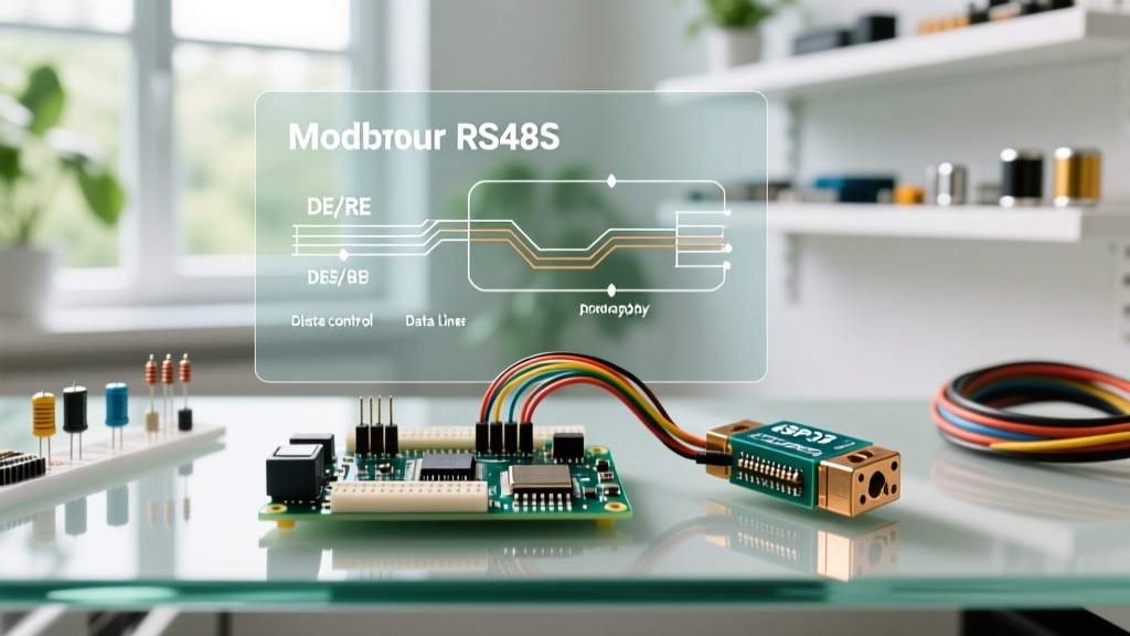
Hardware Layer: Biasing, Termination, and the DE/RE Pin Trap
The most common point of failure in an Arduino RS485 circuit is the physical transceiver module. The ubiquitous HW-519 MAX485 modules (typically costing around $2.50) are barebones implementations lacking essential industrial safeguards.
The Missing Bias and Termination Resistors
RS485 uses differential signaling (A and B lines). When no node is transmitting, the transceiver outputs are in a high-impedance state. Without bias resistors, the A and B lines float, acting as antennas for electromagnetic interference (EMI). The Arduino receiver will interpret this noise as valid start bits, resulting in garbage data and immediate CRC failures.
- Termination: Place a 120Ω resistor across the A and B pins at both physical ends of the RS485 bus to match the cable's characteristic impedance and prevent signal reflections.
- Biasing (Fail-Safe): On the master (Arduino) side, add a 560Ω pull-up resistor from the A line to VCC (5V) and a 560Ω pull-down resistor from the B line to GND. This ensures the bus idles in a logical '1' (Mark state), preventing false start-bit detection.
The DE/RE Switching Delay
Because RS485 is half-duplex, the Arduino must toggle the Driver Enable (DE) and Receiver Enable (RE) pins to switch between transmitting and listening. A fatal error occurs when the Arduino switches the DE pin LOW (to listen for the slave's response) before the final stop bit of the master's request has fully left the UART shift register.
Always call Serial.flush() in your Arduino sketch before pulling the DE/RE pin LOW. This forces the microcontroller to wait until the hardware transmit buffer is completely empty, preventing the truncation of the final CRC byte.Software Timing: The 3.5 Character Rule and Jitter
The Modbus RTU protocol does not use explicit start or end frame characters. Instead, it relies on silent intervals to delineate frames. According to the Modbus Application Protocol Specification, a frame ends when there is a silence of at least 3.5 character times.
At a standard 9600 baud rate (using 8 data bits, no parity, 1 stop bit), one character takes roughly 1.04 milliseconds. Therefore, the inter-frame gap must be at least 3.64 ms. If your Arduino sketch introduces a delay longer than 3.5 characters in the middle of a frame (e.g., due to an interrupt firing or a slow I2C sensor read inside the Modbus callback), the slave will prematurely terminate the frame and return a CRC error.
The SoftwareSerial Catastrophe
Never use the SoftwareSerial library for Modbus RTU at baud rates above 38400. Software serial relies on pin-change interrupts and software timing loops, which introduce severe jitter. This jitter frequently violates the 1.5 character inter-byte maximum timeout, causing the slave to drop the packet. Always route your Modbus traffic through the Arduino's hardware UART pins (e.g., Pins 0/1 on an Uno, or Serial1/Serial2 on a Mega or ESP32).
Decoding ModbusMaster and ArduinoModbus Error Codes
When using popular libraries like Doc Walker's ModbusMaster or the official ArduinoModbus library, the returned error codes are your primary diagnostic clues. Below is a matrix of common errors and their specific hardware root causes.
| Error Name | Hex Code | Meaning | Root Cause & Hardware Fix |
|---|---|---|---|
| Response Timed Out | 0xE0 | Master sent request, received zero bytes back. | Wiring fault, incorrect slave ID, or DE pin stuck HIGH (master is deaf). Check DE/RE pull-down wiring. |
| Invalid CRC | 0xE2 | Response received, but checksum failed. | Missing 120Ω termination resistors causing reflections, or baud rate mismatch causing bit-slip. |
| Invalid Function | 0xE1 | Slave rejected the requested Modbus function code. | Not a wiring error. You are requesting a Holding Register (FC 03) from a device that only supports Input Registers (FC 04). |
| Illegal Data Address | 0xE3 | Register address does not exist on the slave. | Off-by-one addressing error. Modbus addresses are often 0-indexed in software but 1-indexed in PLC manuals. |
Step-by-Step Oscilloscope Diagnostic Workflow
When error codes point to physical layer corruption, a $15 USB logic analyzer or a basic oscilloscope is required. Follow this diagnostic sequence:
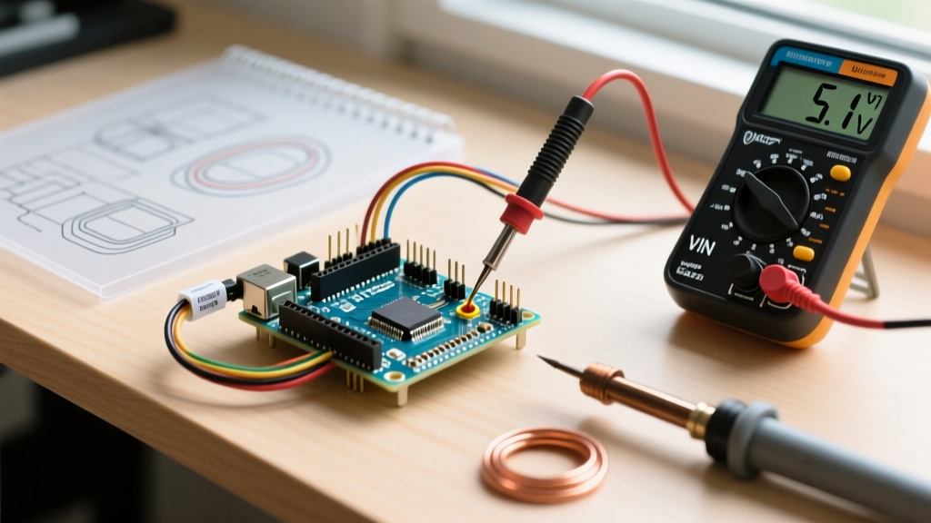
- Verify the Idle State: With no code running, probe the A and B lines. A minus B should read a positive voltage (typically +5V or +3.3V depending on the transceiver). If it reads near 0V, your bias resistors are missing or incorrectly valued.
- Catch the DE/RE Transition: Trigger your scope on the falling edge of the DE pin. Zoom in on the UART TX line. Ensure the DE pin stays HIGH for at least 1 bit-time after the final stop bit of the master's request. If DE falls early, the master is clipping its own transmission.
- Inspect the Slave Echo: Look at the A-B differential signal when the slave replies. If the signal amplitude is severely rounded or exhibits 'ringing' (overshoot/undershoot) at the edges, your cable capacitance is too high for your baud rate, or your termination resistors are missing. Drop the baud rate from 115200 to 9600 to compensate for long cable capacitance.
Advanced Troubleshooting: Ground Loops and Isolation
If your Arduino is powered via a USB connection to a PC, and the Modbus slave is powered by an industrial 24V switching power supply, you are highly susceptible to ground loops. The RS485 standard allows for a common-mode voltage range of -7V to +12V. If the ground potential difference between the Arduino and the industrial sensor exceeds this range, the MAX485 chip will either fail to decode the differential signal or suffer catastrophic silicon failure.
For deployments in 2026 where reliability is non-negotiable, abandon the basic MAX485 chip. Upgrade to an isolated RS485 transceiver like the ADM2483 or ISO3082 (available from Mouser or DigiKey for approximately $4.50 to $6.00). These ICs utilize internal micro-transformers to provide galvanic isolation up to 2500Vrms, completely eliminating ground loop errors and protecting your Arduino's microcontroller from high-voltage transients common in industrial motor-control environments.
Final Diagnostic Checklist
- Are you using Hardware Serial instead of SoftwareSerial?
- Is
Serial.flush()called before toggling the DE/RE pin LOW? - Are 120Ω termination resistors installed at the extreme ends of the bus?
- Is the bus biased with 560Ω resistors to VCC and GND?
- Have you verified the slave's Modbus address offset (0 vs 40001 registry mapping)?
By systematically addressing the physical biasing, respecting the 3.5 character timing rule, and utilizing proper galvanic isolation, you can transform a fragile breadboard prototype into a rock-solid industrial Modbus node.