
The "Cheap Yellow Display" Phenomenon
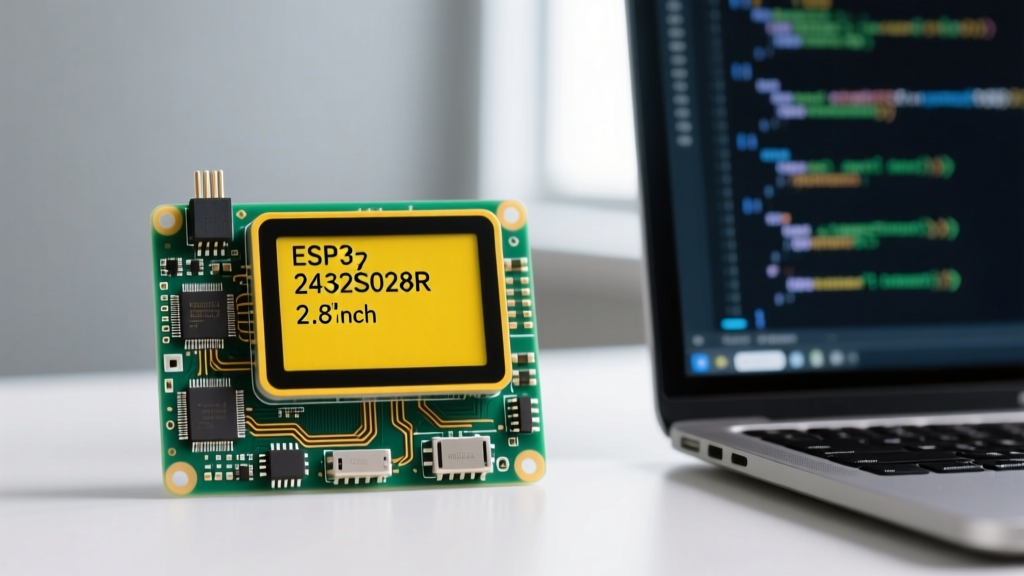
If you have spent any time in the maker, home automation, or IoT communities over the last few years, you have undoubtedly encountered the ESP32 2432S028R. Affectionately dubbed the "Cheap Yellow Display" (CYD) by the community, this board represents a watershed moment in microcontroller accessibility. Retailing for an astonishing $8 to $14 on platforms like AliExpress, it packs an ESP32-WROOM-32 module, a 2.8-inch 320x240 ILI9341 TFT LCD, a resistive touch screen, and a suite of onboard peripherals into a single, USB-powered package.
However, the aggressive price point comes with a well-documented caveat: fragmented documentation. Manufacturers frequently swap out underlying components (like the USB-UART bridge or the backlight control GPIO) between production batches without updating the silkscreen or schematic. This community resource is designed to cut through the noise, providing a definitive, battle-tested guide to the ESP32 2432S028R pinout, software configuration, and hardware quirks based on collective maker insights.
Hardware Anatomy: What Is Actually on the Board?
Before writing a single line of code, it is critical to understand the silicon you are working with. The ESP32 2432S028R is not just a display; it is a highly integrated development board. Below is the component breakdown that dictates how you must route your GPIOs and manage power.
| Component | Model / Spec | Interface | Community Notes |
|---|---|---|---|
| Microcontroller | ESP32-WROOM-32 (Dual-core, 240MHz, 4MB Flash) | N/A | Standard Espressif module; supports Wi-Fi and Bluetooth. |
| Display | 2.8" TFT LCD (320x240) | SPI (ILI9341 Driver) | Excellent color reproduction; requires specific SPI clock tuning. |
| Touch Controller | XPT2046 | SPI (Separate CS) | Resistive touch. Prone to edge-drift; requires software calibration. |
| USB-UART Bridge | CP2102 or CH340 (Batch dependent) | USB to UART | CH340 requires specific drivers on older Windows/macOS builds. |
| Voltage Regulator | AMS1117-3.3 | 5V to 3.3V LDO | Prone to thermal throttling if Wi-Fi and backlight run at 100%. |
The Definitive ESP32 2432S028R Pinout Map
The most common point of failure for beginners is attempting to use standard ESP32 dev board pinouts. The 2432S028R routes its SPI buses and peripheral pins in a highly specific, non-standard manner to accommodate the physical layout of the LCD ribbon cables. Furthermore, the display and the touch controller share the same SPI bus (MISO, MOSI, SCLK) but utilize entirely different Chip Select (CS) pins.
Display and Touch SPI Routing
The ILI9341 display and XPT2046 touch controller are wired to the ESP32’s hardware VSPI bus. Attempting to use software SPI will result in abysmal framerates and touch latency. You must define the following pins in your firmware:
- TFT_MOSI: GPIO 13
- TFT_MISO: GPIO 12
- TFT_SCLK: GPIO 14
- TFT_CS: GPIO 15
- TFT_DC: GPIO 2 (Data/Command)
- TFT_RST: Not connected (Tied to 3.3V via pull-up, use -1 in code)
- TOUCH_CS: GPIO 33
Onboard Peripherals and Sensors
Unlike barebones dev boards, the CYD includes several hardcoded peripherals. Knowing these is essential so you do not accidentally assign a conflicting GPIO in your sketch.
| Peripheral | GPIO Pin | Behavior / Logic |
|---|---|---|
| RGB LED (Red) | GPIO 4 | Active LOW (Write LOW to turn ON) |
| RGB LED (Green) | GPIO 16 | Active LOW |
| RGB LED (Blue) | GPIO 17 | Active LOW |
| LDR (Light Sensor) | GPIO 34 | Input Only (Read via analogRead) |
| Speaker / Audio Out | GPIO 26 | DAC Output (Requires external amp/speaker) |
| MicroSD Card CS | GPIO 5 | Standard SPI CS (Shares VSPI bus) |
Community Warning: The Backlight Pin Lottery
Depending on the manufacturing batch of your ESP32 2432S028R, the backlight control pin (TFT_BL) will either be GPIO 21 or GPIO 27. If your screen remains completely black but the serial monitor shows the sketch is running, or if you get a "white screen of death," swap the backlight pin definition in your code between 21 and 27. The vast majority of 2024+ revisions use GPIO 21.
TFT_eSPI Configuration: Solving the Setup Nightmare
The TFT_eSPI library by Bodmer is the undisputed community standard for driving the ILI9341 on this board. However, it does not auto-detect hardware. You must manually edit the User_Setup.h file before compiling. Failing to do this, or using the wrong driver macro, is the number one reason makers abandon the board.
Locate the User_Setup.h file in your Arduino libraries folder (Documents/Arduino/libraries/TFT_eSPI/User_Setup.h) and replace its contents with the following community-verified configuration block:
// ESP32 2432S028R (CYD) Specific User_Setup.h Defines
#define ILI9341_2_DRIVER
#define TFT_WIDTH  240
#define TFT_HEIGHT 320

#define TFT_MISO 12
#define TFT_MOSI 13
#define TFT_SCLK 14
#define TFT_CS   15
#define TFT_DC    2
#define TFT_RST  -1
#define TFT_BL   21  // Change to 27 if your batch requires it

#define TOUCH_CS 33

#define LOAD_GLCD
#define LOAD_FONT2
#define LOAD_FONT4
#define LOAD_FONT6
#define LOAD_FONT7
#define LOAD_FONT8
#define LOAD_GFXFF

#define SMOOTH_FONT

#define SPI_FREQUENCY  55000000 // 55MHz is the stable sweet spot for this board
#define SPI_READ_FREQUENCY  20000000
#define SPI_TOUCH_FREQUENCY  2500000
Notice the ILI9341_2_DRIVER macro. Many cheap clones use a slightly modified ILI9341 silicon that requires this specific driver flag to handle color inversion and memory addressing correctly. Furthermore, capping the SPI frequency at 55MHz prevents the infamous "screen tearing" and artifacting that occurs when pushing the AMS1117 voltage regulator and ESP32 GPIOs to 80MHz.
Common Failure Modes & Hardware Quirks
Working with the ESP32 2432S028R requires an understanding of its physical limitations. Based on thousands of community deployments, here are the most frequent failure modes and their solutions:
1. Touch Axis Inversion and Drift
The XPT2046 resistive touch controller is notorious for returning inverted X/Y axes or mirrored coordinates depending on how the LCD ribbon is seated. When using the XPT2046_Touchscreen library, you must implement a calibration matrix. Do not rely on raw getTouch() coordinates. Use the Brian Lough CYD GitHub Repository calibration sketch to map the raw touch inputs to the 320x240 pixel grid.
2. The Boot Button Trap (GPIO 0)
The "BOOT" button on the side of the board is hardwired to GPIO 0. On the ESP32, GPIO 0 is a strapping pin that dictates boot modes. If you attempt to use GPIO 0 as a standard input in your sketch and wire it with an internal pull-up, you may cause the ESP32 to enter flash download mode upon a soft reset, resulting in a boot loop. Avoid using GPIO 0 for user inputs in your final firmware.
3. Wi-Fi and Backlight Thermal Throttling
The onboard AMS1117-3.3 LDO is rated for 800mA, but it lacks adequate heatsinking on the PCB copper pours. If you run the Wi-Fi radio at maximum transmission power while simultaneously driving the TFT backlight at 100% PWM, the LDO will overheat and trigger thermal shutdown, causing the ESP32 to brownout and reboot. Solution: Limit your backlight PWM to 75% or route an external 5V supply directly to the board’s 5V header pins to bypass the USB current limits.
Expanding the CYD: I2C and UART Headers
While the board is heavily integrated, it does break out two crucial communication buses via the unpopulated header pins on the edges of the PCB. The CN1 header typically exposes I2C (GPIO 22 SCL, GPIO 27 SDA)—though remember that GPIO 27 might be consumed by the backlight on older revisions. If your backlight is on GPIO 21, GPIO 27 is free for I2C devices like BME280 sensors or RTC modules. The CN2 header exposes UART2 (GPIO 1 TX, GPIO 3 RX), which is perfect for connecting to external microcontrollers, RS485 transceivers, or GPS modules.
Final Thoughts for Makers
The ESP32 2432S028R is a triumph of community-driven reverse engineering. While the lack of official factory documentation can be infuriating, the collective knowledge base has turned this cheap piece of hardware into one of the most versatile MCU platforms available. By respecting the SPI bus routing, carefully managing the LDO thermal limits, and utilizing the correct TFT_eSPI configuration, you can build everything from slick Home Assistant dashboards to standalone weather stations with confidence.