
The Golden Rule of Haptic Hardware
Integrating an Arduino vibration motor into your project is one of the most effective ways to add tactile feedback, silent alerts, or wearable haptics. However, the most common mistake beginners make is wiring the motor directly to the microcontroller's digital I/O pins. The ATmega328P (used in the Arduino Uno and Nano) has an absolute maximum current rating of 40mA per pin, and a recommended operating current of just 20mA. Even a small 3V micro-vibration motor can draw a stall current exceeding 100mA on startup, which will instantly degrade or destroy your Arduino's GPIO pin.
This quick-reference FAQ covers the essential hardware topologies, component selections, and software techniques required to drive vibration motors reliably in 2026.
ERM vs. LRA: Which Vibration Motor for Arduino?
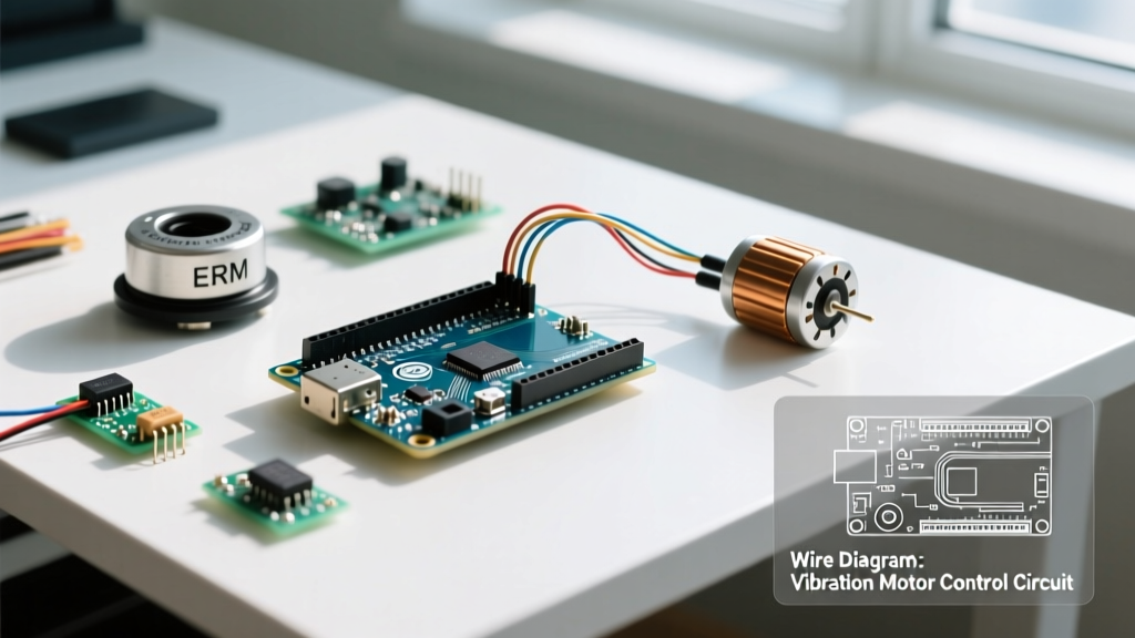
Before wiring anything, you must identify your actuator type. The two dominant technologies are Eccentric Rotating Mass (ERM) and Linear Resonant Actuators (LRA). They require entirely different driving strategies.
| Feature | ERM (Eccentric Rotating Mass) | LRA (Linear Resonant Actuator) |
|---|---|---|
| Mechanism | Off-center weight spun by a DC motor | Voice coil oscillating a magnetic mass on a spring |
| Response Time | Slow (30ms - 50ms to reach full speed) | Ultra-fast (< 10ms) |
| Frequency Control | Amplitude and frequency are linked (PWM) | Amplitude and frequency are decoupled |
| Driver Requirement | Simple NPN Transistor or MOSFET | Dedicated H-Bridge / Haptic Driver IC |
| Typical Cost (2026) | $1.50 - $4.00 | $6.00 - $12.00 (with driver board) |
| Example Model | Precision Microdrives 304-100 | Adafruit DRV2605L Breakout (Product 2305) |
Hardware Wiring & Component FAQ
Q: What is the best transistor to drive a standard ERM motor?
For small 3V to 5V ERM motors drawing under 200mA, a standard NPN BJT like the 2N2222 or 2N3904 is perfectly adequate. You must place a 1kΩ base resistor between the Arduino PWM pin and the transistor base to limit base current to roughly 4mA.
For larger haptic modules or higher-current ERMs, upgrade to a logic-level N-Channel MOSFET like the IRLB8721. MOSFETs are voltage-driven rather than current-driven, meaning they draw virtually zero continuous current from your Arduino pin and handle much higher motor loads without overheating.
Q: Is a flyback diode strictly necessary?
Yes. An ERM motor is an inductive load. When the transistor switches off, the collapsing magnetic field generates a reverse voltage spike (back-EMF) that can exceed 50V, easily frying your transistor or feeding noise back into the Arduino's 5V rail. Solder a standard 1N4148 or 1N4001 diode in parallel with the motor terminals. The cathode (striped end) must face the positive voltage supply, and the anode must face the transistor's collector/drain.
Q: Why does my Arduino reset or brownout when the motor turns on?
This is caused by voltage sag. When the motor starts, it pulls a high inrush current. If you are powering both the Arduino and the motor from the same 5V USB rail or a weak battery, the voltage drops below the ATmega328P's brownout detection threshold (typically 4.3V), triggering a reset.
- Fix 1: Add a 100µF to 470µF electrolytic decoupling capacitor directly across the motor's power rails to supply the instantaneous inrush current.
- Fix 2: Power the motor from a separate battery pack (e.g., 2x AA or a 3.7V LiPo), ensuring the battery's ground is tied to the Arduino's GND to complete the control signal circuit.
Software & PWM Control FAQ
Q: How do I control the vibration intensity of an ERM motor?
You control intensity using Pulse Width Modulation (PWM) via the analogWrite() function. However, not all Arduino pins support PWM. On an Uno/Nano, you must use pins 3, 5, 6, 9, 10, or 11 (marked with a ~ symbol).
Pro-Tip on PWM Frequencies: According to the official Arduino analogWrite() documentation, pins 5 and 6 operate at roughly 980 Hz, while pins 3, 9, 10, and 11 operate at roughly 490 Hz. For haptic motors, the 490 Hz pins are generally preferred as they reduce high-pitched audible whining from the motor coils.
Q: Why does my motor just 'hum' at low PWM values instead of vibrating?
ERMs suffer from static friction. A low PWM duty cycle (e.g., analogWrite(pin, 40)) might not deliver enough average torque to overcome the physical inertia of the off-center weight. The motor will whine but fail to rotate.
The Solution: Use a 'kickstart' routine in your code. Send a 100% duty cycle signal for 20-50 milliseconds to break static friction, then immediately drop to your desired lower PWM value.
const int MOTOR_PIN = 9;

void setup() {
  pinMode(MOTOR_PIN, OUTPUT);
}

void loop() {
  // Kickstart to overcome static friction
  analogWrite(MOTOR_PIN, 255);
  delay(40);

  // Drop to a gentle, continuous rumble
  analogWrite(MOTOR_PIN, 90);
  delay(1000);

  // Turn off
  analogWrite(MOTOR_PIN, 0);
  delay(2000);
}
LRA Motors: The Haptic Driver Requirement
If you are using an LRA for high-definition haptics (like smartphone-style clicks and textures), standard PWM will not work efficiently. LRAs must be driven at their specific mechanical resonance frequency (usually around 175 Hz). Driving them off-resonance results in weak vibration and high power consumption.
To drive an LRA with an Arduino, use a dedicated I2C haptic driver IC like the Texas Instruments DRV2605L. As detailed in the Adafruit DRV2605L Breakout guide, this chip contains a built-in library of over 100 pre-programmed haptic waveforms (like 'Sharp Click', 'Heartbeat', or 'Double Bump') and handles the closed-loop auto-resonance tracking automatically. You simply send an I2C command to trigger the effect, freeing up your MCU's timers and processing power.
Troubleshooting Matrix
| Symptom | Probable Cause | Actionable Fix |
|---|---|---|
| Motor spins, but Arduino freezes or restarts randomly. | Electrical noise (EMI) from motor brushes coupling into the MCU logic lines. | Add a 0.1µF ceramic capacitor directly across the motor terminals. Keep motor wiring physically separated from sensitive sensor wires. |
| Transistor gets too hot to touch. | Using a BJT (like 2N2222) for a motor drawing >300mA, causing high Vce saturation voltage. | Replace the BJT with a logic-level N-Channel MOSFET (e.g., IRLB8721 or FQP30N06L) and add a 10kΩ pull-down resistor on the gate. |
| Motor vibrates continuously, even when Arduino pin is LOW. | Floating gate/base on the transistor picking up ambient EMI. | Add a 10kΩ pull-down resistor between the transistor base/gate and GND to ensure it fully turns off when the MCU pin is LOW. |
| LRA motor feels incredibly weak. | Driving LRA directly with DC or standard PWM instead of AC resonance. | Switch to an I2C Haptic Driver (DRV2605L) or an H-Bridge motor driver capable of outputting bipolar AC waveforms at 175Hz. |
For deeper specifications on motor stall currents and physical dimensions, always consult the manufacturer's datasheet—such as the TI DRV2605L Product Page for IC limits, or your specific motor vendor's technical drawings. Proper component matching ensures your haptic feedback is crisp, reliable, and safe for your microcontroller.