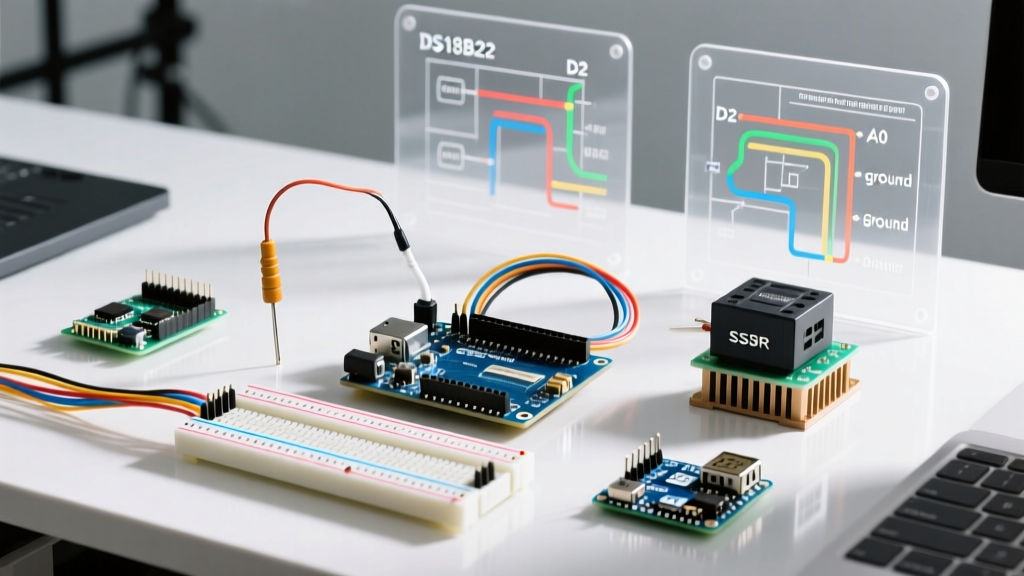

Designing a Robust Arduino Temp Controller
Building a custom Arduino temp controller is a rite of passage for makers, homebrewers, and DIY automation enthusiasts. However, moving from a simple blink sketch to a closed-loop thermal management system requires navigating a minefield of hardware incompatibilities. A mismatched sensor interface, an incorrectly driven relay, or a poorly sampled PID loop can result in oscillating temperatures, destroyed microcontrollers, or even electrical fires.
This comprehensive compatibility guide breaks down the exact microcontrollers, sensors, actuators, and software libraries you need to build a professional-grade temperature controller in 2026, focusing on real-world failure modes and precise hardware pairings.
Microcontroller Selection: Uno R4 vs. ESP32-S3
While the classic Arduino Uno R3 has been the default for decades, modern thermal control demands better ADC resolution and hardware PWM capabilities.
- Arduino Uno R4 Minima ($22): Features a 14-bit ADC, which is a massive upgrade for reading analog thermistors directly without external amplification. However, its default PWM frequency and limited memory can bottleneck complex PID calculations with high-resolution HMI displays.
- ESP32-S3 DevKit ($12 - $16): The undisputed king for advanced thermal control. The ESP32-S3 offers dual-core processing, native Wi-Fi for remote telemetry, and crucially, the
ledc(LED Control) hardware peripheral. This allows you to generate precise, low-frequency PWM signals required for Solid State Relays (SSRs) without blocking the main execution loop.
Expert Recommendation: If your Arduino temp controller requires internet logging or drives multiple SSRs simultaneously, bypass the AVR architecture entirely and use an ESP32-S3 mapped to the Arduino IDE environment.
Temperature Sensor Compatibility Matrix
Choosing the right sensor dictates your wiring topology, library dependencies, and maximum temperature threshold. Below is a compatibility matrix for the most common sensors used in thermal projects.
| Sensor / Module | Interface | Accuracy | Max Temp | Est. Cost (2026) |
|---|---|---|---|---|
| DS18B20 (Waterproof) | 1-Wire | ±0.5°C | 125°C | $3.50 - $5.00 |
| Adafruit MAX31865 (PT100 RTD) | SPI | ±0.1°C | 850°C | $14.95 |
| MAX31855 (K-Type Thermocouple) | SPI | ±2.0°C | 1350°C | $9.00 - $12.00 |
| BME280 | I2C | ±1.0°C | 85°C | $6.00 |
Deep Dive: RTD vs. Thermocouple Interfaces
For high-precision applications like espresso machine boiler control or sous-vide, the PT100 RTD via the MAX31865 is the gold standard. According to the Adafruit MAX31865 Guide, you must use a 3-wire or 4-wire PT100 probe to allow the MAX31865 to calculate and cancel out the resistance of the copper lead wires. Using a 2-wire probe will introduce a static offset error of roughly 1°C to 3°C depending on cable length.
For extreme heat (kilns, forges), the MAX31855 K-Type is mandatory. However, thermocouples require cold-junction compensation. The MAX31855 handles this internally, but it relies on the NIST Thermocouple Database linearization tables. Ensure your SPI clock speed is capped at 5MHz; pushing it to 10MHz on long jumper wires will result in corrupted 32-bit data packets and erratic temperature spikes.
The Output Stage: Mechanical Relays vs. Solid State Relays
The most common point of failure in an Arduino temp controller is the actuator stage. Driving a heating element requires switching high-voltage AC, and the compatibility between your microcontroller's output pins and the relay is critical.
The PWM Frequency Trap
If you use the standard Arduino analogWrite() function, the default PWM frequency on pins 5 and 6 is roughly 980Hz, and 490Hz on other pins. This is fundamentally incompatible with standard AC Solid State Relays (SSRs).
Standard zero-crossing SSRs (like the ubiquitous SSR-25DA or the industrial Crydom D2425) are designed to switch AC mains at the zero-voltage crossing point to minimize electromagnetic interference (EMI). They expect a steady DC control signal or a very low-frequency PWM (1Hz to 10Hz). Feeding a 490Hz PWM signal into an SSR will cause it to behave erratically, overheat, and potentially fail in a 'closed' (always ON) state, creating a severe fire hazard.
Critical Fix: To use an SSR with an Arduino Uno, you must use software-based time-proportioning (detailed in the PID section below) or use a hardware timer library likeTimerOneto drop the PWM frequency to 2Hz. If using an ESP32, configure theledcperipheral to output a 1Hz - 5Hz PWM signal natively.
SSR Leakage Current and Snubber Circuits
Generic, low-cost SSRs (often $4 online) suffer from high 'off-state' leakage current (up to 5mA). While this won't shock you, it can keep low-wattage heating elements or indicator lamps faintly glowing. Furthermore, if your Arduino temp controller switches inductive loads (like a compressor motor or a transformer), the voltage spike upon turn-off will destroy the SSR's internal TRIAC. You must wire an RC snubber network (typically a 100Ω resistor in series with a 0.1µF capacitor) across the SSR output terminals to suppress these transients.
PID Software Compatibility and Time-Proportioning
For anything beyond a simple bang-bang (on/off) thermostat, you need Proportional-Integral-Derivative (PID) control. The industry standard is Brett Beauregard's Arduino PID Library.
However, a major compatibility issue arises when pairing this library with SSRs. The PID library outputs a value between 0 and 255. If you map this directly to an analog pin, you hit the 490Hz PWM trap mentioned earlier.
Implementing Time-Proportioning
The correct software architecture for an Arduino temp controller using an SSR is Time-Proportioning. Instead of outputting a high-frequency duty cycle, the PID output dictates how many milliseconds the SSR stays ON during a fixed time window (usually 1 to 5 seconds).
- Set a
WindowSizeof 2000ms (2 seconds). - Set the PID Output Limits to
0and2000. - In your main loop, track the
millis()timestamp. - If the current time within the window is less than the PID Output value, set the SSR digital pin
HIGH. Otherwise, set itLOW.
This results in a 0.5Hz to 1Hz switching frequency, which is perfectly compatible with zero-crossing AC SSRs and ensures the AC sine wave is cleanly chopped without generating massive EMI.
Display & UI Compatibility
Monitoring your thermal loop requires a display, but I2C address conflicts and memory limits often derail projects.
- 16x2 I2C LCD (PCF8574 backpack): Cheap ($3) and easy to wire, but the PCF8574 I2C expander is notoriously slow. Polling it too frequently inside a fast PID loop (e.g., every 50ms) will cause I2C bus lockups and freeze the microcontroller. Limit LCD updates to once every 500ms.
- Nextion HMI Displays (NX4827T043): The professional choice for 2026. These communicate via UART (Serial). You offload all UI rendering and button debouncing to the Nextion's internal processor. Your Arduino simply reads and writes integer variables via serial commands, freeing up massive amounts of CPU cycles for tight PID sampling loops.
Critical Failure Modes and Edge Cases
Even with compatible hardware, environmental factors can break an Arduino temp controller. Watch out for these specific edge cases:
1. Thermocouple Ground Loops
The MAX31855 thermocouple amplifier assumes the thermocouple bead is electrically isolated. If you are measuring the temperature of a grounded metal surface (like an aluminum heater block or an espresso boiler) and the bare thermocouple wire touches the chassis, it creates a ground loop. This injects 50/60Hz mains noise directly into the SPI data lines, resulting in the MAX31855 throwing a 0x04 (Short to GND) error. Solution: Always use grounded, mineral-insulated (MI) thermocouple probes where the metal sheath is isolated from the internal K-type wires.
2. 1-Wire Parasitic Power Failures
The DS18B20 supports 'parasitic power' mode (drawing power from the data line), requiring only two wires. However, when calculating temperatures above 100°C, the sensor's internal ADC draws a sudden spike of current that the 4.7kΩ pull-up resistor cannot supply, causing the sensor to brown out and return an 85°C default error code. Solution: For any Arduino temp controller dealing with heat, always use the 3-wire VDD power mode.
3. USB Ground Bounce
If you are powering your Arduino via USB while simultaneously switching a high-wattage AC heater via an SSR on the same workbench, the EMI can travel through the earth ground, causing voltage spikes on the Arduino's USB 5V rail. This will randomly reset your microcontroller. Always use an isolated DC-DC buck converter to power the Arduino from a separate 12V or 24V supply in high-load thermal environments.
Summary
Building a reliable Arduino temp controller requires looking beyond basic pin compatibility. By pairing an ESP32-S3 or Uno R4 with a MAX31865 RTD sensor, driving a zero-crossing SSR via time-proportioning, and utilizing the Brett Beauregard PID library, you create a thermal management system capable of holding temperatures within ±0.2°C. Respect the physics of AC switching, isolate your grounds, and your DIY controller will rival commercial $500 industrial units.