
The Hardware Reality Behind digitalRead()
Executing a digital read in Arduino environments is often the very first thing a maker learns. You wire a button or a sensor, call digitalRead(pin), and expect a clean HIGH or LOW. However, as the maker ecosystem has evolved from the classic 5V ATmega328P to modern 3.3V powerhouses like the ESP32-S3 and Raspberry Pi RP2040, the hardware compatibility landscape has fractured. What works flawlessly on an Arduino Uno R3 can instantly destroy the GPIO bank of an Arduino Nano RP2040 Connect or an ESP32 dev board.
To master sensor compatibility, you must look past the Arduino IDE abstraction and understand the silicon-level voltage thresholds: $V_{IH}$ (Voltage Input High) and $V_{IL}$ (Voltage Input Low). According to the Arduino Official Reference, digitalRead() simply queries the hardware register mapped to that pin. If the voltage on the pin exceeds the microcontroller's specific $V_{IH}$ threshold, it registers as HIGH. If it drops below $V_{IL}$, it registers as LOW. The danger zone lies in the undefined region between these thresholds, and the catastrophic zone lies above the absolute maximum ratings.
Microcontroller Logic Level Compatibility Matrix
Before wiring a 5V industrial proximity sensor or a 3.3V Hall effect module to your board, consult this compatibility matrix. Understanding these thresholds prevents erratic reads and silicon damage.
| Microcontroller / Board | Operating Voltage | $V_{IH}$ (Min HIGH) | $V_{IL}$ (Max LOW) | 5V Tolerant? |
|---|---|---|---|---|
| ATmega328P (Uno R3, Nano) | 5.0V | 3.0V (0.6 x Vcc) | 1.5V (0.3 x Vcc) | Yes (Native 5V) |
| RA4M1 (Arduino Uno R4) | 5.0V | 3.5V | 1.5V | Yes (Header level) |
| ESP32 / ESP32-S3 | 3.3V | 2.31V (0.7 x Vio) | 0.99V (0.3 x Vio) | NO |
| RP2040 (Nano Connect, Pico) | 3.3V | 2.0V | 0.8V | NO |
| SAMD21 (Arduino Zero, MKR) | 3.3V | 2.31V | 0.99V | NO |
As highlighted in the RP2040 Hardware Datasheet, applying 5V to a non-tolerant 3.3V pin forward-biases the internal ESD protection diode. This creates a low-resistance path from the 5V sensor output directly into the 3.3V internal power rail, potentially causing latch-up, thermal shutdown, or permanent silicon destruction if the current exceeds 15mA.
Bridging the Gap: Level Shifter Compatibility
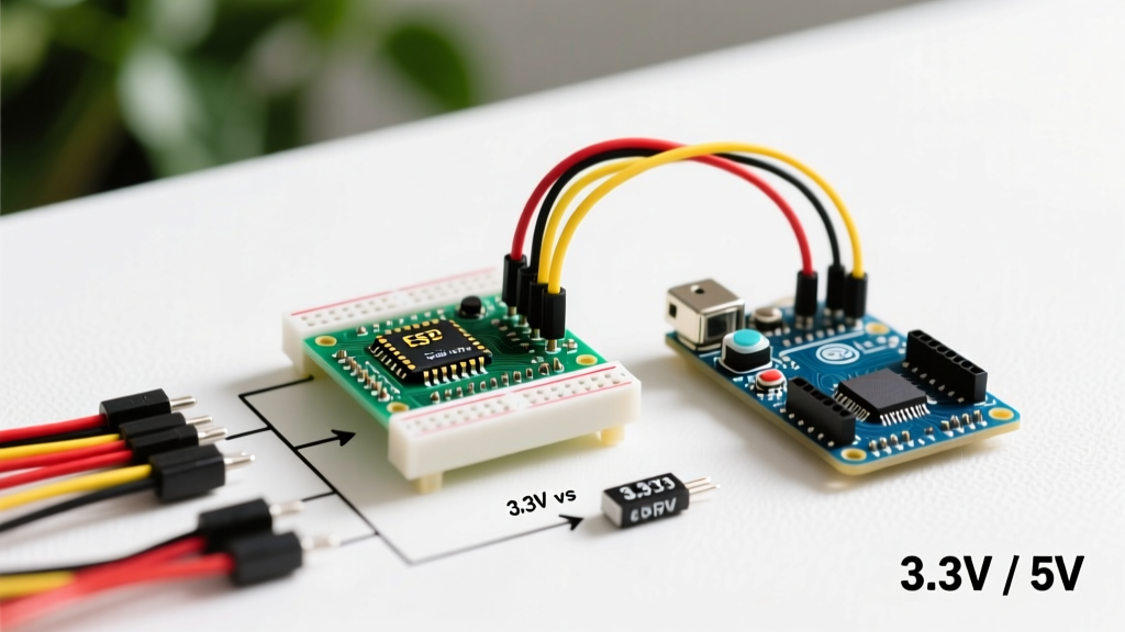
When your sensor outputs 5V but your microcontroller demands 3.3V, you need a logic level translator. Not all level shifters are created equal, and choosing the wrong one for a simple digitalRead() operation can introduce signal ringing or slow rise times.
1. BSS138 MOSFET Breakout Boards
Cost: ~$2.50 per 4-channel module.
Best For: I2C, open-drain outputs, and bidirectional communication.
Compatibility Verdict: Conditional. BSS138 shifters require pull-up resistors on both the high-voltage (HV) and low-voltage (LV) sides. If your 5V sensor has a push-pull output (actively drives both HIGH and LOW), the BSS138 will struggle to pull the line down to a clean $V_{IL}$ quickly, leading to slow fall times and potential read errors at high frequencies.
2. TXS0108E (Auto-Directional)
Cost: ~$3.00 per 8-channel module.
Best For: SD card interfaces, SPI, and short-wire GPIO.
Compatibility Verdict: Poor for long wires. The TXS0108E features internal edge accelerators. While great for high-speed SPI, these accelerators react violently to the parasitic capacitance of long sensor cables (over 1 meter). This causes severe signal ringing, which the Arduino interprets as multiple rapid HIGH/LOW transitions, completely breaking your digital read logic.
3. SN74LV1T34 (Single-Supply Auto-Translator)
Cost: ~$0.45 per single-gate IC (SOT-23 package).
Best For: Push-pull digital reads, industrial sensors, long cable runs.
Compatibility Verdict: Superior. Powered by 3.3V, the SN74LV1T34 accepts inputs up to 5.5V and translates them to a clean 3.3V CMOS output without requiring external pull-ups or suffering from edge-accelerator ringing. For serious 2026 maker projects interfacing 5V industrial limit switches to 3.3V MCUs, this is the gold standard.
Internal vs. External Pull-Up Resistors: The Capacitance Trap
The Arduino INPUT_PULLUP mode is a staple of button-reading tutorials. However, relying on internal pull-ups for remote sensors is a frequent source of compatibility failures. As noted in SparkFun's Logic Levels Tutorial, understanding impedance is critical for signal integrity.
- Internal Pull-Ups: Typically range from 20kΩ to 50kΩ on AVR, and 50kΩ to 80kΩ on the RP2040.
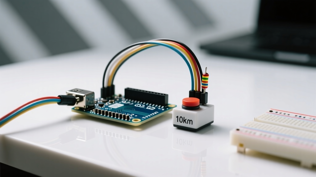
- External Pull-Ups: Typically 4.7kΩ or 10kΩ discrete resistors.
The Edge Case: Imagine reading a 5V magnetic reed switch located 4 meters away, connected via standard CAT5 cable. The cable introduces roughly 200pF of parasitic capacitance. If you use the RP2040's internal 60kΩ pull-up, the RC time constant ($\tau = R \times C$) becomes 12 microseconds. If the switch bounces or the environment has high EMI, the pin voltage will rise so slowly that it lingers in the undefined region between $V_{IL}$ and $V_{IH}$, causing the microcontroller to register dozens of phantom digitalRead() triggers.
Pro-Tip: For any sensor wired more than 50cm away from the microcontroller, disableINPUT_PULLUP. Instead, configure the pin asINPUTand solder a 4.7kΩ external pull-up resistor directly at the sensor's output terminal. This drops the RC time constant to under 1 microsecond, ensuring crisp, noise-immune logic transitions.
Troubleshooting Common digitalRead() Failures
When your serial monitor spams random 1s and 0s, or a sensor refuses to register, check these specific failure modes:
Floating Pins and High-Impedance Noise
If a pin is configured as INPUT but left physically unconnected, it acts as an antenna. In environments with switching power supplies or AC mains nearby, the pin will capacitively couple 50/60Hz noise, crossing the $V_{IH}$ threshold randomly. Fix: Never leave unused GPIO pins floating. Configure them as OUTPUT and write them LOW, or enable internal pull-downs if the MCU supports it (like the ESP32).
Ground Bounce in Mixed-Voltage Systems
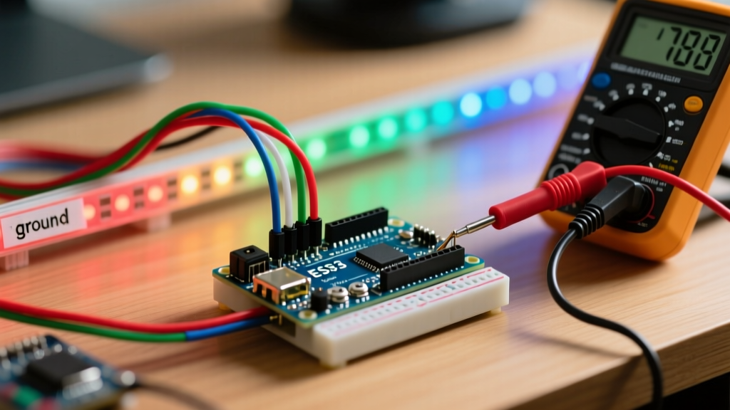
When reading a 5V sensor powered by a separate 5V buck converter, while the Arduino is powered via USB, the ground potentials are rarely identical. A 0.4V ground offset between the sensor's ground and the Arduino's ground effectively shifts the sensor's output voltage. A sensor outputting 0.2V for LOW might be read as 0.6V by the Arduino. While usually safe, in marginal 3.3V systems, this can push the LOW state dangerously close to the $V_{IL}$ threshold. Fix: Always tie the ground of the external sensor power supply directly to the Arduino's GND pin using a thick (20 AWG or lower) wire to minimize ground loop impedance.
Mechanical Switch Bounce
Software debouncing is common, but hardware compatibility dictates that some switches bounce for up to 20 milliseconds. If your digitalRead() loop runs without a delay or hardware interrupt filtering, a single button press will register as 40 distinct presses. Fix: Implement a 0.1µF ceramic capacitor in parallel with the switch, combined with a 1kΩ series resistor, creating a hardware low-pass filter that physically prevents the voltage from oscillating.
Summary Checklist for 2026 Projects
- Verify Logic Levels: Never assume a modern Arduino board is 5V. Check the specific MCU datasheet for $V_{IH}$ and 5V tolerance.
- Select the Right Shifter: Use SN74LV1T34 for push-pull digital reads; avoid TXS0108E for long cable runs.
- Respect Capacitance: Use 4.7kΩ external pull-ups for remote sensors; reserve internal pull-ups for on-board buttons.
- Unify Grounds: Ensure all external sensor power supplies share a low-impedance common ground with the MCU.
By treating digitalRead() not just as a software function, but as a physical measurement of voltage thresholds, impedance, and capacitance, you eliminate the most elusive hardware bugs in modern microcontroller design.