
The Architecture Divide: Why Board Selection Matters for FastLED
When driving addressable LEDs like the WS2812B or SK6812, the Arduino FastLED library remains the undisputed gold standard in the maker community. However, as we navigate the hardware landscape in 2026, the days of relying solely on the 16MHz ATmega328P (Arduino Uno/Nano) are behind us. Modern installations demand higher frame rates, parallel outputs, and wireless connectivity, pushing makers toward the ESP32 family and the Raspberry Pi RP2040.
The core compatibility challenge lies in how these LEDs communicate. The WS2812B protocol is notoriously strict, requiring precise timing pulses (T0H = 0.4µs, T1H = 0.8µs). Different microcontroller architectures handle these microsecond delays in fundamentally different ways, leading to unique compilation errors, flickering, and DMA conflicts if not configured correctly.
Board-by-Board Compatibility Matrix
Before wiring up your next installation, consult this compatibility matrix to understand how FastLED interacts with modern silicon. According to the FastLED official wiki, hardware peripheral support is critical for non-blocking LED updates.
| Board Family | Architecture | Clock Speed | FastLED Timing Method | Known Quirks & Limits |
|---|---|---|---|---|
| Arduino Uno/Nano | AVR (8-bit) | 16 MHz | CPU Cycle Counting (Bit-bang) | Blocks all interrupts; limits IR/Serial usage. |
| ESP32 (Original) | Xtensa (32-bit) | 240 MHz | RMT / I2S DMA | WiFi DMA conflicts if I2S is used; 8 RMT channels. |
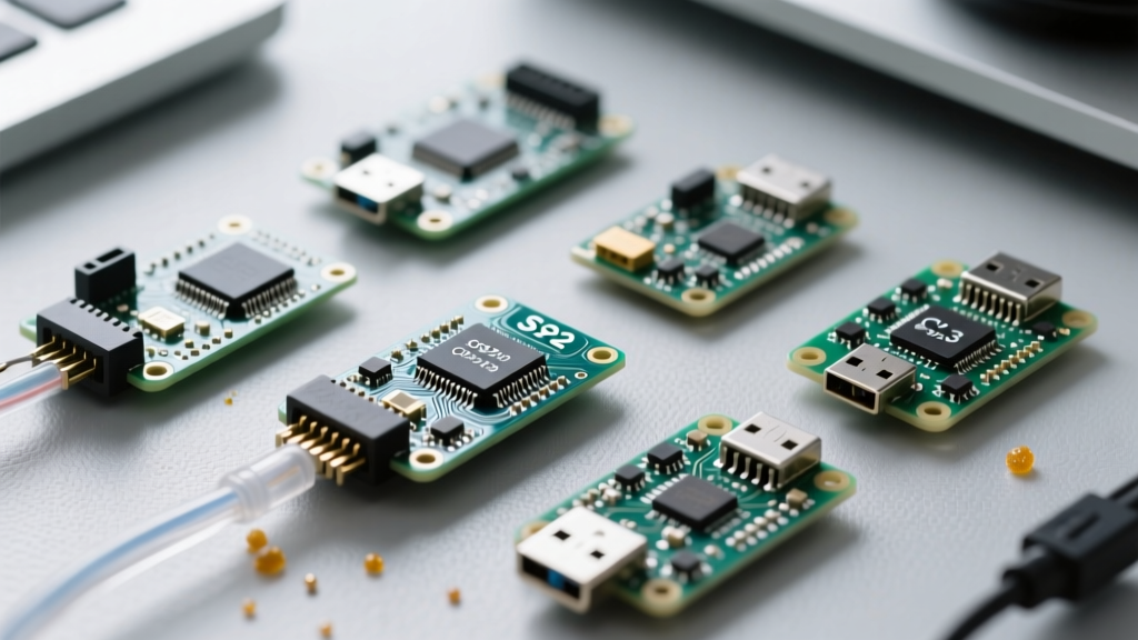
| ESP32-S3 / C3 | Xtensa / RISC-V | 240 / 160 MHz | RMT Peripheral | Fewer TX channels (4 on S3, 2 on C3); requires pin mapping. |
| Raspberry Pi Pico | ARM Cortex-M0+ | 133 MHz | PIO (Programmable I/O) | Flawless timing; uses 1 PIO state machine per data line. |
| Teensy 4.1 | ARM Cortex-M7 | 600 MHz | OctoWS2811 DMA | Overkill for small projects; massive parallel output capability. |
Deep Dive: ESP32 and the RMT vs. I2S Conflict
The ESP32 is the most popular board for IoT-connected LED matrices, but it is also the most frequent source of Arduino FastLED compatibility headaches. Early versions of FastLED on the ESP32 used the I2S peripheral to DMA (Direct Memory Access) data to the LEDs. While efficient, this caused catastrophic conflicts when the user enabled WiFi or Bluetooth, as the ESP32's WiFi stack also relies heavily on DMA and I2S interrupts.
The RMT Solution
To solve this, modern FastLED implementations default to the RMT (Remote Control Transceiver) peripheral. The RMT is designed specifically for generating precise pulse sequences without CPU intervention. As detailed in the Espressif RMT API documentation, the original ESP32 features 8 independent RMT channels, allowing you to drive 8 separate LED strips in parallel without blocking the main CPU cores or interfering with WiFi.
Pro-Tip for ESP32-S3 Users: The ESP32-S3 only has 4 dedicated RMT Transmit channels. If your project requires more than 4 parallel data lines, you must either use an ESP32 (original) or implement a multiplexing IC like the 74HC595 to route the signals.
Forcing RMT in your sketch:
If you experience WiFi dropouts when updating your LEDs, force the RMT driver by adding this definition at the very top of your sketch, before including the library:
#define FASTLED_ESP32_USE_RMT
#include <FastLED.h>
Deep Dive: RP2040 and the PIO Advantage
The Raspberry Pi Pico (RP2040) has revolutionized addressable LED control thanks to its PIO (Programmable I/O) blocks. Unlike the ESP32's RMT, the RP2040's PIO consists of tiny, independent state machines that execute custom assembly instructions.
When you compile an Arduino FastLED sketch for the RP2040, the library loads a specialized WS2812 assembly program into a PIO state machine. This yields absolute perfection in timing. Because the PIO runs entirely decoupled from the dual Cortex-M0+ cores, you can run heavy computational tasks, audio processing, or USB serial communication on the main cores while the PIO flawlessly bit-bangs the LED data in the background. The RP2040 features two PIO blocks with 4 state machines each, allowing up to 8 perfectly synchronized, independent LED strips.
Voltage Level Translation: The Hidden Compatibility Killer
A massive 80% of 'flickering' or 'random color' issues reported in maker forums are not software bugs, but hardware voltage mismatches. The WS2812B datasheet specifies that a logic HIGH on the DIN pin must be at least 0.7 × VDD. If you power the LEDs with 5V, the data line must reach 3.5V to register as a '1'.
The 3.3V Logic Problem
Both the ESP32 and RP2040 operate at 3.3V logic. When they output a HIGH signal, they only send 3.3V to the data line. This is below the 3.5V threshold required by the 5V-powered WS2812B, resulting in unstable data transmission, especially on the first LED in the chain.
Hardware Fixes (Ranked by Reliability)
- The SN74AHCT125 Level Shifter (Best): This specific IC costs around $0.60 and is designed to translate 3.3V logic up to 5V safely. Wire the ESP32/RP2040 GPIO to the input, power the IC with 5V, and connect the output to the LED DIN. This is the industry standard for permanent installations.
- The 1N4148 Diode Trick (Quickest): If you lack a level shifter, place a standard 1N4148 signal diode on the 5V power line just before the first LED's VDD pin (cathode pointing toward the LED). This drops the LED's VDD to roughly 4.3V. Consequently, the 0.7 × 4.3V threshold becomes 3.01V, making the 3.3V logic signal perfectly valid. Note: This only works for short runs of less than 50 LEDs due to voltage sag.
- Sacrificial Pixel (Legacy): Power the very first LED with 3.3V logic, and use its DOUT (which will be 3.3V) to feed the rest. This is highly unreliable and not recommended for modern builds.
For comprehensive wiring standards, the Adafruit NeoPixel UberGuide strongly advocates for dedicated level shifting and proper power injection to prevent data corruption.
Power Injection and Current Mathematics
Software compatibility means nothing if your hardware browns out. A single WS2812B pixel drawing maximum white (RGB 255,255,255) pulls exactly 60mA.
- 100 LEDs: 6 Amps (Requires a 5V 10A power supply, ~$15)
- 500 LEDs: 30 Amps (Requires a 5V 40A power supply, ~$35)
- 1000 LEDs: 60 Amps (Requires a 5V 60A+ power supply, ~$55)
Crucial Rule: Never route 60A through a standard breadboard or thin jumper wires. You must use a dedicated power distribution bus with at least AWG 10 wire for the main trunk, and inject 5V and GND into the LED strip every 50 to 100 pixels using AWG 18 wire to prevent voltage sag, which causes the far end of the strip to glow yellow or turn off entirely.
Troubleshooting Common FastLED Compilation Errors
When switching between board architectures in the Arduino IDE or PlatformIO, you will inevitably hit compilation walls. Here is how to bypass the most common Arduino FastLED errors:
1. '#error FastLED requires a 32-bit processor'
Cause: You are trying to compile an ESP32 or ARM-specific FastLED sketch while the IDE is still set to an 8-bit AVR board (like the Uno), or you have selected the wrong ESP32 variant in the Boards Manager.
Fix: Go to Tools > Board and ensure the exact ESP32 or RP2040 dev board is selected. Update your FastLED library to version 3.6.0 or newer via the Library Manager.
2. 'RMT Channel Allocation Failed'
Cause: You have defined more CRGB arrays and FastLED.addLeds instances than the ESP32 has available RMT TX channels (e.g., trying to run 5 strips on an ESP32-C3, which only supports 2).
Fix: Reduce the number of parallel data pins, or switch to a board with more hardware channels like the original ESP32 or Teensy 4.1.
3. 'Undefined reference to FastLED'
Cause: A missing namespace or incorrect include order, often seen when mixing FastLED with ESPHome or ArduinoJSON.
Fix: Ensure #include <FastLED.h> is declared globally at the top of the file, and verify that your CRGB leds[NUM_LEDS]; array is not trapped inside a local function scope.
Final Verdict for 2026 Installations
If you are building a simple, low-cost wearable or a basic desk lamp, the classic AVR Arduino Nano remains a charming, bit-banging workhorse. However, for any installation exceeding 200 LEDs, or requiring WiFi/Bluetooth integration, the ESP32-S3 (using RMT) or the RP2040 (using PIO) are the definitive choices. Pair them with an SN74AHCT125 level shifter and robust power injection, and your Arduino FastLED projects will run flawlessly for years.