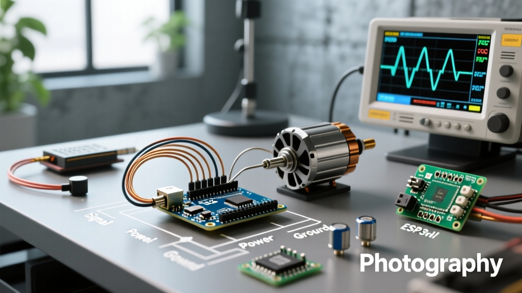

Quick Reference: Arduino to BLDC ESC Wiring Matrix
Controlling a DC brushless motor with an Arduino requires an intermediary Electronic Speed Controller (ESC) or a dedicated Field Oriented Control (FOC) driver. The ATmega328P cannot source the phase currents required by a BLDC motor. Below is the standard wiring matrix for a hobby-grade ESC using the Arduino Servo library.
| ESC Wire (JR/Futaba Standard) | Arduino Uno/Nano Pin | Function & Voltage Level | Critical Notes |
|---|---|---|---|
| Signal (White/Yellow) | Pin 9 (PWM capable) | 50Hz PWM Control Signal (0-5V) | Must use 50Hz. Standard analogWrite (490Hz) will fail. |
| Ground (Black/Brown) | GND | Common Ground Reference (0V) | Shared ground is mandatory for signal integrity. |
| 5V BEC (Red) | 5V or VIN (Unplug USB!) | Power for Arduino (5V DC) | Disable BEC if using high-cell LiPo (4S+) to prevent thermal failure. |
| Battery + / - (Thick Red/Black) | Power Supply (LiPo/PSU) | Main Motor Power (7.4V - 22.2V+) | Use XT60/XT90 connectors. Add 1000uF decoupling capacitor. |
Frequently Asked Questions (FAQ)
Can I connect a BLDC motor directly to an Arduino?
No. A brushless DC motor requires sequential commutation of three phases (A, B, C) using high-current MOSFETs. The ATmega328P microcontroller on an Arduino Uno has an absolute maximum current rating of 40mA per I/O pin, and a total package limit of 200mA. A standard 2212 BLDC motor draws between 10A and 30A under load. Attempting a direct connection will instantly destroy the microcontroller. Furthermore, a spinning BLDC motor acts as a generator; the resulting back-EMF voltage spikes can easily exceed the 5V logic threshold, frying the MCU via its internal protection diodes. You must use an ESC (for trapezoidal control) or a 3-phase inverter shield (for sinusoidal FOC control).
How do I calibrate a hobby ESC with an Arduino?
Unlike standard DC motors, hobby ESCs require throttle endpoint calibration to understand the exact microsecond pulse widths representing 0% and 100% throttle. Because Arduino PWM timing can vary slightly from standard RC transmitters, calibration is mandatory.
- Prepare the Sketch: Upload a sketch using the Arduino Servo library that outputs
writeMicroseconds(2000)(Maximum Throttle). - Power the Arduino: Power the Arduino via USB. Do not connect the LiPo battery to the ESC yet.
- Connect Battery: Plug the LiPo into the ESC. The ESC will emit a startup tone, followed by a special programming tone (usually two quick beeps).
- Set Minimum Throttle: Within 3 seconds of the special tone, change your sketch to output
writeMicroseconds(1000)(Minimum Throttle) and upload/restart. - Confirm: The ESC will emit a confirmation musical tone, indicating the 1000us-2000us range is saved.
Pro-Tip: Never calibrate an ESC with the propeller or load attached. A miscalibration can cause the motor to spin at 100% power unexpectedly.
Why is my BLDC motor stuttering, beeping, or failing to arm?
The most common failure mode when interfacing a DC brushless motor with an Arduino is using the wrong PWM frequency. The standard Arduino analogWrite() function outputs a PWM signal at approximately 490 Hz (or 980 Hz on pins 5 and 6). Hobby ESCs are designed to read RC receiver signals, which operate at exactly 50 Hz (a 20ms period with a 1ms to 2ms high pulse). If you feed 490 Hz into an ESC, it will interpret the signal as noise, fail to arm, and emit an endless error beep.
The Fix: You must use the official Arduino Servo Library. Despite the name, this library generates the exact 50Hz pulse train required by ESCs. Use myservo.attach(9) and myservo.writeMicroseconds(1000) instead of analogWrite.
What is the difference between Hobby ESCs and FOC Drivers?
As of 2026, makers have two distinct paths for BLDC control, depending on the application requirements:
- Hobby ESCs (Trapezoidal Commutation): Use standard 50Hz PWM. They are cheap ($12 - $25), robust, and ideal for drones, RC cars, and basic propulsion. However, they suffer from torque ripple at low speeds and lack precise position control.
- FOC Drivers (Field Oriented Control): Use advanced algorithms to drive the motor with smooth sinusoidal waves. Boards like the SimpleFOC Shield or B-G431B-ESC1 communicate with the Arduino via I2C or CAN bus. FOC provides zero-cogging low-speed torque, high efficiency, and precise closed-loop position control, making it mandatory for robotics, gimbals, and haptic feedback devices.
How do I choose the right BEC (Battery Eliminator Circuit)?
Most hobby ESCs include a linear BEC to step down the main battery voltage to 5V to power the Arduino. However, linear BECs dissipate excess voltage as heat. The thermal dissipation is calculated as: Heat (Watts) = (Battery Voltage - 5V) * Current Draw.
If you use a 4S LiPo (14.8V) and your Arduino draws 50mA, the BEC dissipates (14.8 - 5) * 0.05 = 0.49W, which is manageable. But if you add sensors, displays, or servos drawing 500mA, the BEC must dissipate 4.9W. Most internal linear BECs will thermally shut down or melt at this level. Rule of thumb: If running above 3S (11.1V) LiPo, physically cut the red 5V BEC wire on the ESC signal lead and power the Arduino using a dedicated switching UBEC or a separate 5V buck converter.
2026 Component Recommendations & Pricing
Selecting the right driver depends on your project's precision requirements. Below is a curated list of reliable BLDC drivers compatible with Arduino ecosystems.
| Component Model | Type | Continuous Current | Best Use Case | Approx. Price (2026) |
|---|---|---|---|---|
| Hobbywing Skywalker 40A | Standard ESC (PWM) | 40A (Burst 55A) | Drones, RC boats, basic propulsion | $18.50 |
| Turnigy Multistar Elite 30A | Standard ESC (PWM) | 30A (Burst 40A) | Lightweight UAVs, budget builds | $14.00 |
| SimpleFOC Shield V2.0.4 | FOC Driver (I2C/SPI) | 2A - 3A (Depends on PSU) | Robotics, gimbals, precision actuators | $49.00 |
| TI DRV8316EVM | Integrated FOC (SPI) | 8A Peak | Industrial prototyping, high-efficiency | $65.00 |
Common Failure Modes and Edge Cases
When scaling from a breadboard prototype to a deployed BLDC system, watch for these specific hardware edge cases:
- Ground Loop Resets: High phase currents switching through the ESC create massive ground bounce. If the Arduino shares a long, thin ground wire with the ESC, the voltage reference will fluctuate, causing the ATmega328P to brownout and reset. Always use thick, short ground wires or a star-ground topology.
- Desync at High RPM: Hobby ESCs rely on back-EMF zero-crossing to time commutation. If your Arduino commands a sudden, aggressive acceleration ramp, the rotor may lag behind the stator field, causing 'desync' (the ESC loses track of the rotor position and stops). Implement software acceleration limits (e.g., increase throttle by max 5 microseconds per loop iteration).
- Capacitor Starvation: ESCs require a low-ESR electrolytic capacitor (typically 100uF to 470uF, rated for 25V+) soldered directly across the main power pads. Without it, long power wires act as inductors, causing voltage spikes that trigger the ESC's overvoltage protection or destroy the MOSFETs.
For advanced users looking to move beyond basic PWM velocity control, exploring TI's brushless motor driver architecture and implementing closed-loop PID control via the SimpleFOC library will yield vastly superior torque and efficiency metrics.