
The I2C Bus Bottleneck: Why Address Configuration Matters
When building complex environmental monitoring stations, power-distribution telemetry arrays, or multi-axis robotics, the Inter-Integrated Circuit (I2C) bus is the default communication protocol for most microcontroller sensors. However, the 7-bit addressing scheme native to I2C limits you to 128 theoretical addresses, with roughly 112 usable in practical applications. The real bottleneck occurs when you need to deploy multiple identical sensors—such as four BME280 environmental modules across a greenhouse array. If you do not properly configure custom I2C addresses in Arduino projects, your sketch will experience address collisions, resulting in corrupted data or complete bus lockups.
This configuration guide details the hardware modifications, software initialization routines, and electrical design rules required to successfully manage multi-sensor I2C arrays on AVR, ARM, and ESP32-based Arduino boards in 2026.
Hardware-Level Address Modification in Arduino Sensors
Most modern I2C breakout boards include physical hardware pads or jumper pins that allow you to toggle the least significant bits (LSBs) of the sensor's I2C address. By bridging these pins to either logic HIGH (3.3V) or logic LOW (GND), you alter the hexadecimal address the sensor responds to on the bus.
Common Sensor Address Configurations
Below is a reference matrix for the most frequently used sensors in Arduino ecosystems, detailing their default addresses, alternative addresses, and the specific physical pins required for reconfiguration.
| Sensor Model | Function | Default Hex | Alt Hex(es) | Config Pin(s) |
|---|---|---|---|---|
| Bosch BME280 | Temp/Humidity/Pressure | 0x77 | 0x76 | SDO |
| TI INA219 | Current/Power Monitor | 0x40 | 0x41 to 0x4F | A0, A1 |
| InvenSense MPU6050 | 6-Axis IMU | 0x68 | 0x69 | AD0 |
| ST VL53L0X | Time-of-Flight LiDAR | 0x29 | Software Defined | XSHUT |
| Adafruit TCS34725 | Color Light Sensor | 0x29 | None (Hardware) | N/A |
Case Study: Modifying the TI INA219 Current Sensor
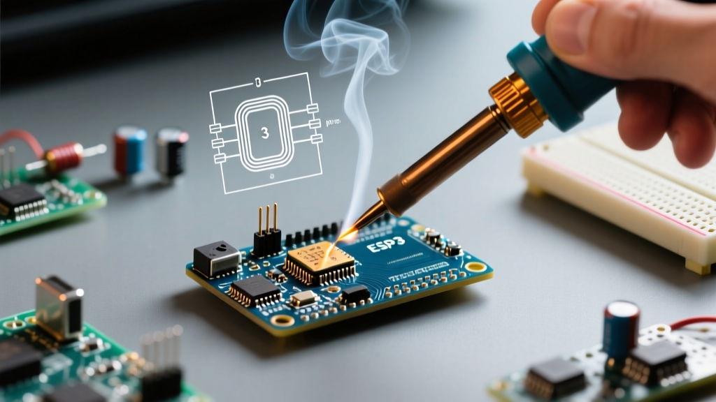
The Texas Instruments INA219 is a staple for Arduino power-logging projects. Out of the box, the A0 and A1 jumper pads on standard breakout boards are left floating or pulled low, yielding the default address of 0x40. By using a fine-tip soldering iron to bridge A0 to VCC, you shift the address to 0x41. Because there are two configuration pins, you can mathematically derive up to 16 unique addresses (0x40 through 0x4F), allowing you to monitor 16 independent power rails on a single Arduino I2C bus without multiplexing.
Software Configuration: Initializing Multiple Addresses in Arduino IDE
Once the hardware addresses are physically set, your Arduino sketch must instantiate separate objects for each sensor and pass the correct hexadecimal address during the begin() initialization phase. Relying on default parameters will cause the Arduino Wire library to poll the wrong address, returning NaN (Not a Number) values.
#include <Wire.h>
#include <Adafruit_BME280.h>

// Instantiate distinct objects for each sensor
Adafruit_BME280 bme_zone1;
Adafruit_BME280 bme_zone2;

void setup() {
  Serial.begin(115200);
  Wire.begin();

  // Initialize with explicit I2C addresses
  if (!bme_zone1.begin(0x77)) {
    Serial.println(F("Zone 1 BME280 failed at 0x77"));
    while (1);
  }
  if (!bme_zone2.begin(0x76)) {
    Serial.println(F("Zone 2 BME280 failed at 0x76"));
    while (1);
  }
}

void loop() {
  Serial.print(F("Zone 1 Temp: ")); Serial.println(bme_zone1.readTemperature());
  Serial.print(F("Zone 2 Temp: ")); Serial.println(bme_zone2.readTemperature());
  delay(2000);
}
According to the official Arduino Wire Library Reference, the Wire.begin() function initializes the I2C bus as a master. When dealing with multiple sensors, it is critical to call Wire.begin() only once in the setup() loop before initializing individual sensor objects to prevent bus state resets.
Overcoming Identical Sensor Collisions: The TCA9548A Multiplexer
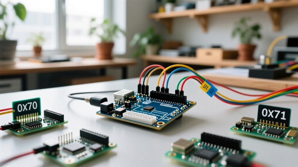
What happens when you need to use five ST VL53L0X Time-of-Flight sensors, but they all share a hardcoded default address of 0x29 and lack hardware address pins? The solution is the Texas Instruments TCA9548A I2C Multiplexer. This chip acts as a traffic controller, routing the master Arduino I2C signals to one of eight isolated downstream channels.
Expert Insight: The TCA9548A communicates via its own I2C address (default 0x70). You send a control byte to the multiplexer to open a specific channel (0-7), effectively isolating the colliding sensors on separate physical buses while sharing the same SDA/SCL master lines.To configure this in Arduino, you bypass standard sensor initialization and instead write directly to the multiplexer's control register using Wire.beginTransmission(0x70). The Adafruit TCA9548A Learn Guide provides excellent baseline code for channel switching, which is essential for robotics arrays requiring simultaneous spatial mapping without address conflicts.
Critical Hardware Design Rules for I2C Arrays
Configuring addresses in software is only half the battle. Scaling an I2C bus to 10 or more devices introduces severe electrical challenges that will crash your Arduino if ignored.
1. The Pull-Up Resistor Parallel Problem
I2C is an open-drain protocol requiring pull-up resistors on the SDA and SCL lines. Most commercial breakout boards include 10kΩ or 4.7kΩ surface-mount pull-up resistors. When you wire five sensors in parallel, those resistors are also placed in parallel. Five 10kΩ resistors in parallel result in an equivalent resistance of 2kΩ. While 2kΩ is generally acceptable for 5V Arduino boards, it can violate the maximum sink current limits of 3.3V microcontrollers like the ESP32 or Arduino Due, pulling the logic LOW voltage (VOL) above the strict 0.4V threshold required for reliable data recognition.
2. Bus Capacitance and Signal Degradation
Every sensor, wire, and breadboard contact adds parasitic capacitance to the I2C bus. The authoritative NXP UM10204 I2C-bus specification strictly mandates that total bus capacitance must not exceed 400 pF for Standard (100 kHz) and Fast-mode (400 kHz) operations. If your multi-sensor array uses long ribbon cables or excessive breadboard jumper wires, the RC time constant will increase, rounding off the square-wave clock signals and causing ACK (Acknowledge) failures.
- Keep traces short: Maintain I2C wire runs under 30cm (12 inches) for 400kHz operation.
- Use twisted pairs: Route SDA and SCL as a twisted pair to minimize inductive crosstalk.
- Drop the clock speed: If you must run long cables for remote greenhouse sensors, force the Arduino Wire library to 100kHz or even 50kHz using
Wire.setClock(100000);to give the signal more time to rise.
Troubleshooting I2C Address Collisions
If your multi-sensor array is returning corrupted data or failing to initialize, deploy an I2C Scanner sketch before modifying your main application logic. An I2C scanner iterates through all 127 possible addresses and reports which ones acknowledge. If you see the same address appearing twice, or if your configured alternative address fails to show up, you have a hardware configuration error.
- Verify Solder Bridges: Use a digital multimeter in continuity mode to ensure your SDO or A0 pads are genuinely connected to VCC or GND, and not suffering from a cold solder joint.
- Check Voltage Logic Levels: Mixing 5V Arduino Unos with 3.3V sensors (like the BME280) without a logic level shifter (e.g., NXP PCA9306) can result in the sensor failing to recognize the address polling bytes.
- Monitor Power Draw: Ten sensors polling simultaneously can cause voltage droops on the 3.3V regulator of a standard Arduino Nano. Ensure your power supply can deliver at least 500mA of clean DC current.
Mastering custom I2C address configuration in Arduino transforms a restrictive bus into a highly scalable telemetry network. By combining precise hardware jumper modifications, robust software instantiation, and strict adherence to electrical capacitance limits, you can reliably deploy massive sensor arrays for any advanced maker or industrial IoT application.