
The Golden Rule of Motor Control
Critical Warning: An Arduino Uno (ATmega328P) GPIO pin can safely source or sink only 20mA (absolute maximum 40mA). A standard SG90 micro servo draws up to 700mA under stall conditions. Connecting a motor directly to an Arduino pin will permanently destroy the microcontroller's silicon trace. Always use a dedicated motor driver or transistor switching circuit.
When you attempt to control motor Arduino circuits, the gap between theoretical code and physical reality is often defined by electrical noise, voltage drops, and current starvation. This diagnostic guide breaks down the most common failure modes for DC, stepper, and servo motors, providing exact multimeter measurements and hardware swaps to get your project moving.
Diagnostic Matrix: Symptom vs. Root Cause
| Symptom | Probable Root Cause | Hardware Fix |
|---|---|---|
| Arduino randomly resets when motor starts | Voltage brownout on the 5V rail due to high inrush current. | Separate motor power supply; add 1000µF electrolytic capacitor. |
| DC motor hums but does not spin | Insufficient voltage reaching the motor terminals due to driver voltage drop. | Upgrade from L298N to TB6612FNG MOSFET driver. |
| Stepper motor misses steps or vibrates | Current limit (VREF) set too low, or acceleration profile too aggressive. | Tune A4988/DRV8825 potentiometer; lower code acceleration. |
| Servo twitches erratically at idle | PWM signal noise or missing common ground reference. | Tie all GNDs together; use shielded cable for PWM signal. |
Deep Dive: DC Motor Voltage Drop Errors
The most ubiquitous error when beginners try to control motor Arduino setups involves the legendary L298N dual H-bridge. While cheap (often under $3.00), the L298N relies on bipolar junction transistor (BJT) Darlington pairs. This architecture inherently suffers from a 1.5V to 2.0V voltage drop across the chip.
The 5V Motor Fallacy
If you power an L298N with a 5V USB battery pack to drive a 5V DC motor, the motor will only receive roughly 3.0V. The motor will either stall or spin with zero torque. To fix this with an L298N, you must supply at least 7.5V to the driver's VCC terminal.
The Modern Solution: TB6612FNG
For low-voltage projects (3.3V to 5V logic and motors), abandon the L298N. The TB6612FNG uses MOSFET architecture, resulting in a negligible voltage drop (typically < 0.5V at 1A). It costs slightly more (around $4.50 to $6.00 for a breakout board) but delivers vastly superior efficiency and thermal performance. For further reading on modern H-bridge topologies, review the Adafruit Motor Shield V2 documentation, which utilizes I2C-controlled PWM chips to completely offload motor timing from the main MCU.
Stepper Motor Jitter: Tuning the A4988 VREF
When using an A4988 stepper motor driver, missed steps and violent shaking are almost always traced to an improperly set VREF (voltage reference). The VREF dictates the maximum current delivered to the stepper coils.
Step-by-Step VREF Calibration
- Identify Motor Rating: Check your NEMA 17 datasheet. Assume a rated current of 1.5A per phase.
- Calculate Target VREF: For the A4988, the formula is
VREF = Current Limit / 2. Therefore, 1.5A / 2 = 0.75V. - Prepare Multimeter: Set your digital multimeter to DC Voltage (2V range). Power the driver's logic (VDD) with 5V, but do not connect the high-voltage motor supply (VMOT) yet.
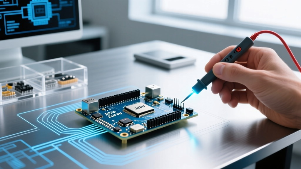
- Measure: Place the black probe on the driver's GND pin and the red probe on the metal shaft of the trim potentiometer (the VREF test point).
- Adjust: Using a ceramic or plastic jeweler's screwdriver (metal shafts alter the magnetic field and capacitance, skewing readings), turn the pot until the multimeter reads exactly 0.75V.
Pro-Tip: If your stepper motor becomes too hot to touch (exceeding 60°C / 140°F), your VREF is too high, or you are driving a high-impedance motor without series/parallel wiring adjustments.
Servo Brownouts and Inductive Kickback
Servos like the MG996R draw massive transient currents—often exceeding 2.5A for milliseconds when starting under load or stalling. If you share the Arduino's 5V regulator for both the MCU and the servo, this inrush current will cause a voltage sag, triggering the ATmega328P's brownout detection (BOD) and resetting your sketch.
The Capacitor Buffer Strategy
To stabilize the rail, solder a 470µF to 1000µF electrolytic capacitor directly across the VCC and GND wires at the servo connector. Additionally, place a 0.1µF (100nF) ceramic capacitor in parallel to filter high-frequency switching noise. This dual-capacitor approach acts as a localized energy reservoir, supplying the instantaneous current spike without dragging down the main 5V rail.
Flyback Diodes for Brushed DC Motors
If you are switching a brushed DC motor via a single MOSFET (like an IRLZ44N) instead of an H-bridge, you must include a flyback diode. When power is cut, the motor's collapsing magnetic field generates a massive reverse voltage spike (inductive kickback) that will punch through the MOSFET's drain-source junction. Wire a 1N4007 diode in reverse bias across the motor terminals (cathode/stripe to V+, anode to MOSFET drain). For integrated shield solutions, the official Arduino Motor Shield R3 handles these flyback protections internally via its L298P chip and onboard clamping diodes.
Multimeter Troubleshooting Flowchart
When a motor fails to respond to your code, bypass the software and verify the physics. Follow this diagnostic sequence with your multimeter:
- Step 1: Verify Logic Power. Measure between the Arduino 5V pin and GND. It must read 4.8V - 5.1V. If it reads 4.2V, your USB cable is too thin or your PC port is current-limited.
- Step 2: Check Common Ground. Measure the resistance (Ohms) between the Arduino GND and the Motor Driver GND. It must read < 1.0Ω. A floating ground will result in erratic PWM behavior.
- Step 3: Validate PWM Signal. Switch your multimeter to AC Voltage (or use an oscilloscope/logic analyzer). Probe the designated PWM pin while the sketch runs. You should see a fluctuating voltage representing the duty cycle (e.g., ~2.5V on a 50% duty cycle 5V pin).
- Step 4: Measure Driver Output. With the motor disconnected, measure the DC voltage across the driver's output terminals (OUT1 and OUT2). It should match your motor supply voltage (minus the driver's inherent voltage drop) when commanded to full speed.
Summary
Mastering how to control motor Arduino circuits requires respecting the boundaries of microcontroller I/O limits and understanding the physics of inductive loads. By upgrading to MOSFET-based drivers for DC motors, precisely tuning VREF for steppers, and buffering servo power rails with adequate capacitance, you eliminate 95% of hardware-level errors before they ever reach your code.